
English Version
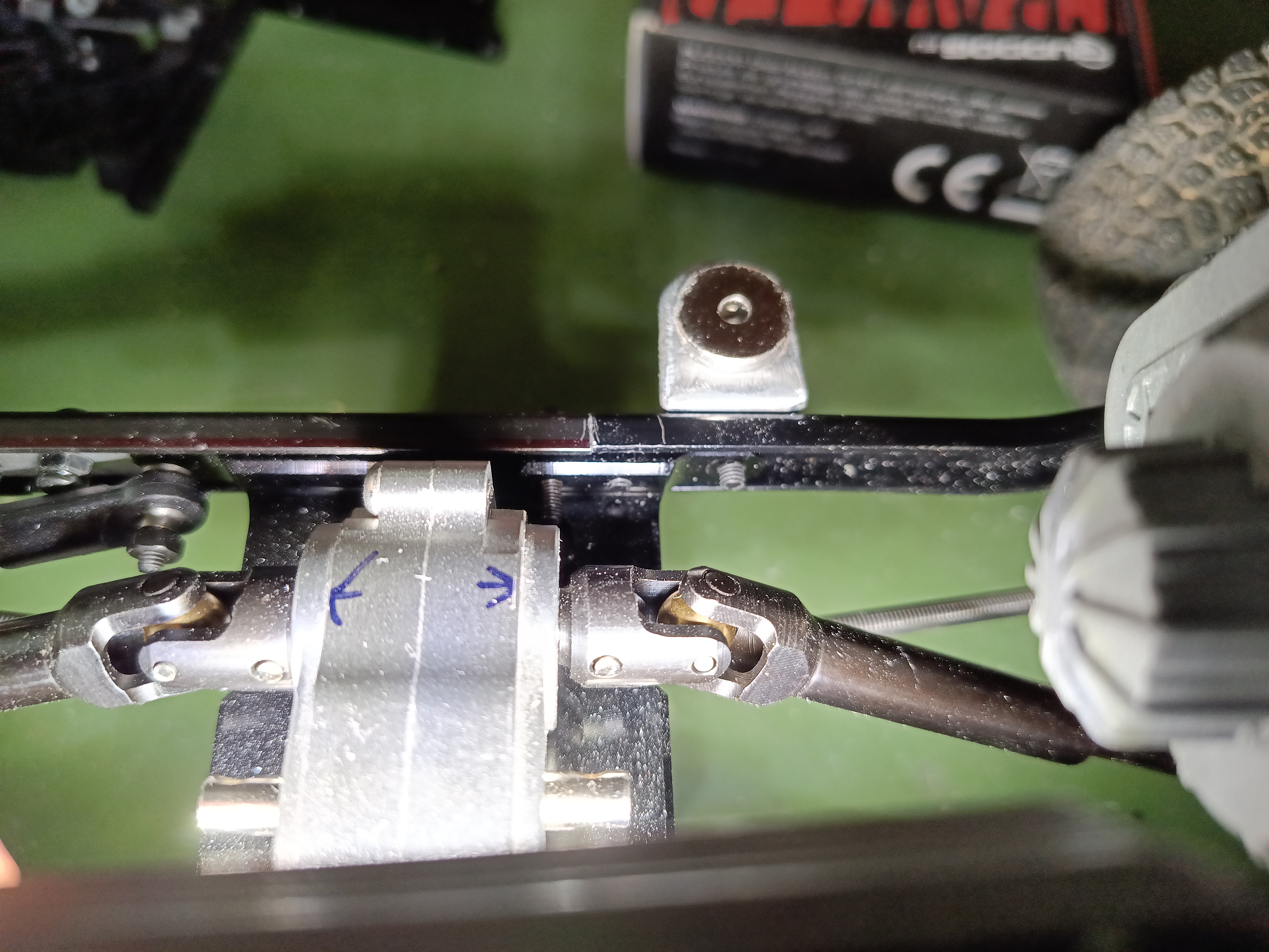
Nach der Vorstellung erster Details im letzten Beitrag, heute eine nähere Betrachtung der Bauweise. Wegen des Radstandes von ca. 330 mm konnte mein Standardrahmen, ein SCX10-Clon, nicht unverändert eingebaut werden. Daher habe ich vier Rahmenprofile verwendet und unterschiedlich lang abgeschnitten. Die Verbindungstelle liegt im Bereich des Unterfahrschutzes, auf dem das Verteilergetriebe sitzt. Das mittlere Rahmenteil ist ursprünglich das abgesägte, hintere Element des SCX10 Rahmenprofiles. Die Bohrungsabstände sind identisch wie am Unterfahrschutz. Diese Bauweise hatt ich auch schon am Rat Comanche verwendet und das Heckteil aus einem Rahmenrest hier als Mittelteil weiterverwendet. Wichtig vor dem sägen ist, die Aufteilung der Bohrungen und des Unterfahrschutzes korrekt aufeinander abzustimmen. Einmal falsch gesägt und schon ist ein neues Rahmenset fällig.
Sicher sind auch andere, als die von mir beschriebene Bauweise denkbar. Da ich aber auf einen vollständigen, unverbauten Innenraum Wert lege, habe ich das Mittelteil entsprechend verlängert. Bei einer anderen Vorgehensweise würde auch nur die Verlängerung des geraden Heckprofils ausreichen.
Für solche Umbauten am besten gleich mindestens zwei identische Rahmensets beschaffen. In meinem Fall waren es wohl zwei Hersteller, weil die Profile im Zehntelbereich variierten. Das wird aber nur bei dieser Entfernung sichtbar, ist also höchstens ein optisches Problem.
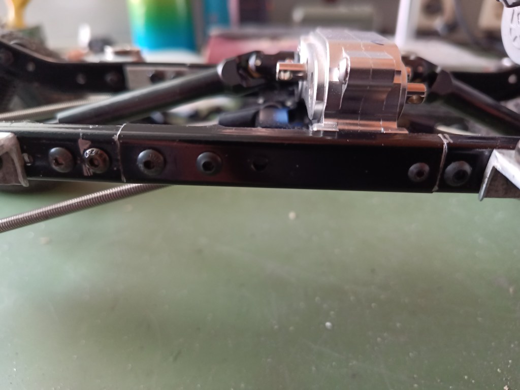
Lediglich ein selbstgebautes Verbindungsteil war so erforderlich, um das Heck mit dem Mittelteil zu verschrauben. Dazu wurde je ein Loch neu in den Rahmen gebohrt.
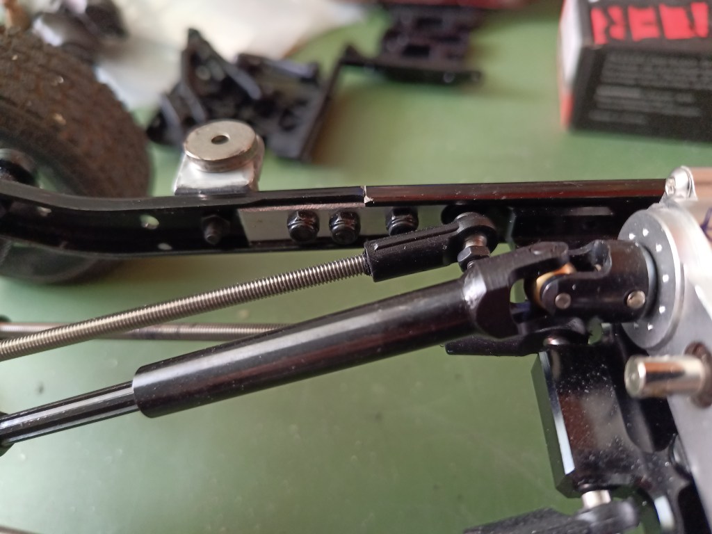
Vorne sind alle Löcher im Rahmen vorhanden, um stabil mit dem Unterfahrschutz verbunden zu werden.
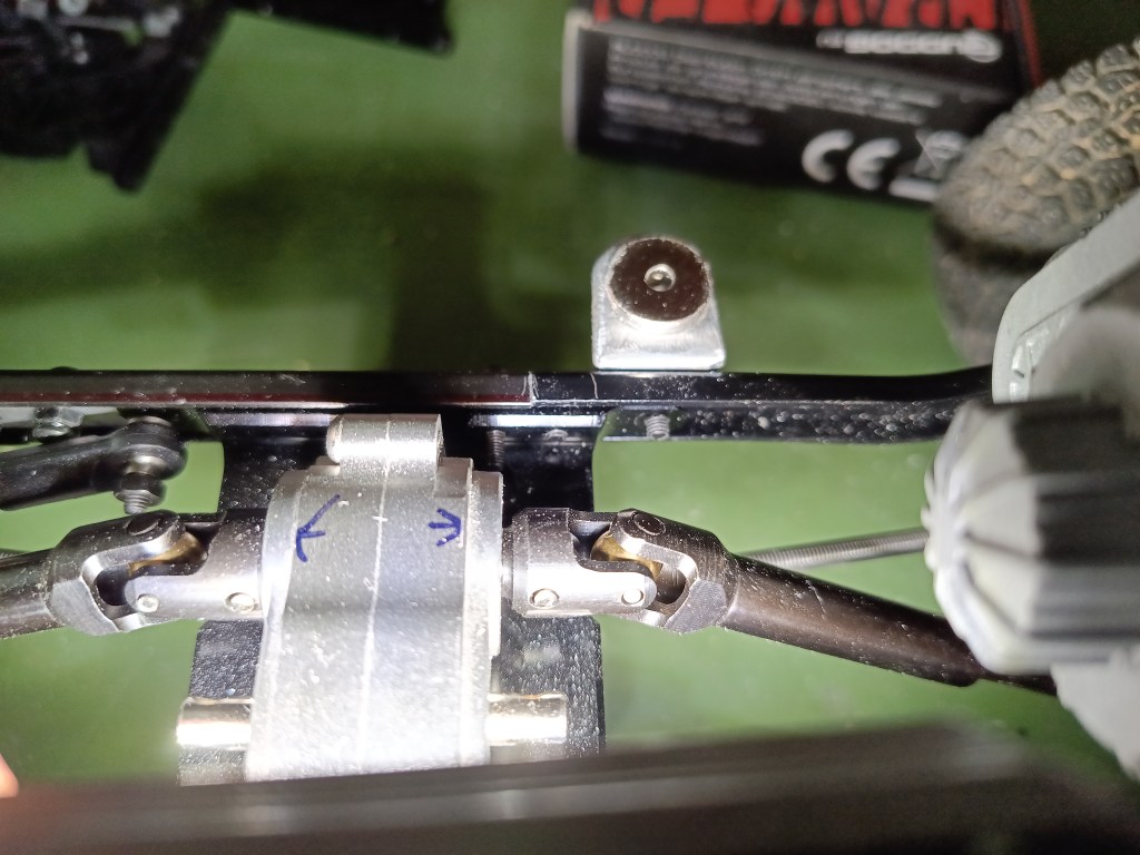
Der SCX10 Unterfahrschutz hat ja beidseitig ein Profil, dass formschlüssig im Rahmenprofil sitzt und es so stabilisiert.
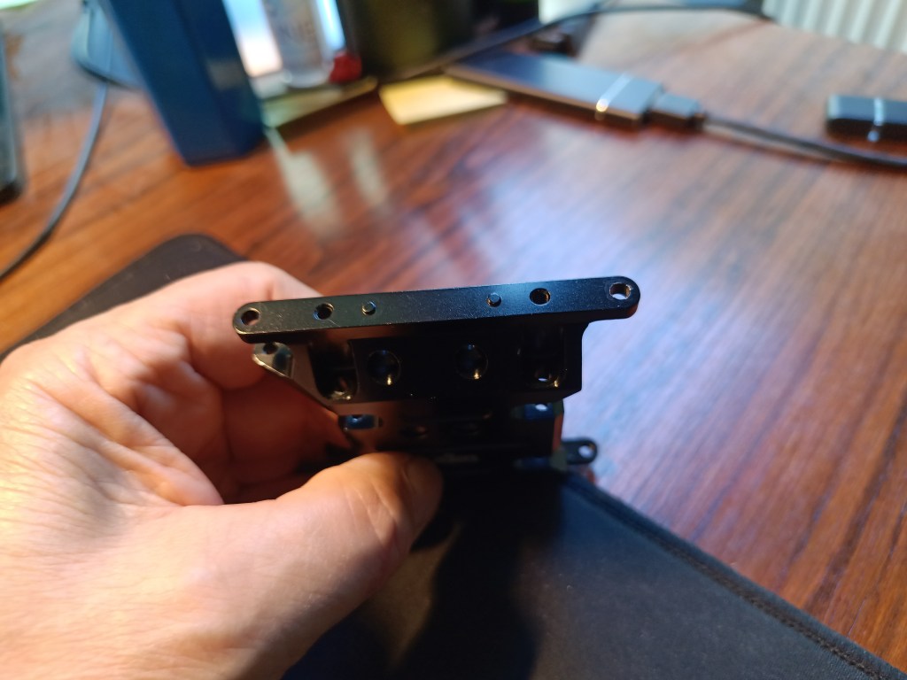
Am Rahmen sind, unter der späteren Bodengruppe, vier Traversen verschraubt. Unten sitzt ein Magnet. Hier von unten sichtbar. Darauf sitzt ein Gegenstück, dass später in der Bodengruppe verklebt wird.
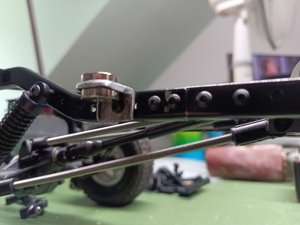
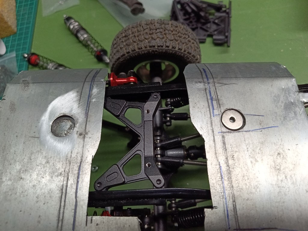
Nachfolgend rechts sichtbar. Von oben ist ein geformtes Blech aufgelötet, das den Magnet unsichtbar macht. Die Bodengruppe soll zusätzlich weitere Profile erhalten, um eine realistische Optik zu bekommen. Wie ich das in Blech realisiere ist noch offen. Einprägen wäre mein Favorit, muss aber noch ausgetüftelt werden. Eine Idee dafür habe ich zumindest. Ich werde von meinen diesbezüglichen Versuchen sicher berichten.
Wird schnellstmöglich fortgesetzt…
English Version
The Chassis and Initial Details of My Ford Raptor Design
After presenting the initial details in the last post, today I’ll take a closer look at the construction. Due to the wheelbase of approximately 330 mm, my standard frame—an SCX10 clone—could not be installed as-is. Therefore, I used four frame profiles and cut them to different lengths. The joint is located in the area of the underbody guard, on which the transfer case sits. The center frame section is originally the sawed-off rear element of the SCX10 frame profile. The hole spacing is identical to that on the underbody guard. I had already used this construction method on the Rat Comanche and reused the rear section—made from a frame scrap—as the center section here. It’s important to correctly align the hole layout with that of the underbody guard before cutting. One wrong cut, and you’ll need a whole new frame set.
Of course, other construction methods besides the one I’ve described are possible. However, since I value having a completely unobstructed interior, I extended the center section accordingly. With a different approach, simply extending the straight rear profile would suffice.
For modifications like this, it’s best to procure at least two identical frame sets right from the start. In my case, they were likely from two different manufacturers because the profiles varied in the center section. However, this is only visible at this distance, so it’s at most a cosmetic issue.
All that was needed was a custom-made connector to bolt the rear section to the center section. To do this, a new hole was drilled in each side of the frame.
At the front, all the holes in the frame are already in place to ensure a secure connection to the underbody guard.
The SCX10 underbody protection has a profile on both sides that fits snugly into the frame profile, thereby stabilizing it.
Four cross members are bolted to the frame beneath where the floor assembly will later be located. A magnet is mounted at the bottom, visible here from below. A counterpart sits on top of it, which will later be glued into the floor assembly.
This is visible on the right below. A shaped sheet metal piece is soldered on from above, concealing the magnet. The floor assembly will also feature additional profiles to achieve a realistic appearance. How I’ll implement this in sheet metal is still up in the air. Embossing would be my preference, but I still need to work out the details. At least I have an idea for it. I’ll be sure to report on my experiments in this regard.
Will be continued as soon as possible…
Translation, with the kind support of deepl.com

