English Version
Die Tage werden kürzer, das nasskalte Wetter lädt nur bedingt zum Aufenthalt im Freien ein. Eigentlich die perfekte Zeit zum Basteln. Im Moment bin ich aber eher etwas träge und suche meinen Leitfaden. Die Suche nach Lösungen und der noch vor mir liegende Bauumfang dämpfen etwas die Baulust. Trotzdem bleibt die Freude, wenn Arbeitsschritte gelingen. Ich baue ja nicht nach einem Plan, der Konstruktions- und Bautechnisch realisiert wurde. So auch die nachfolgenden Ergebnisse.
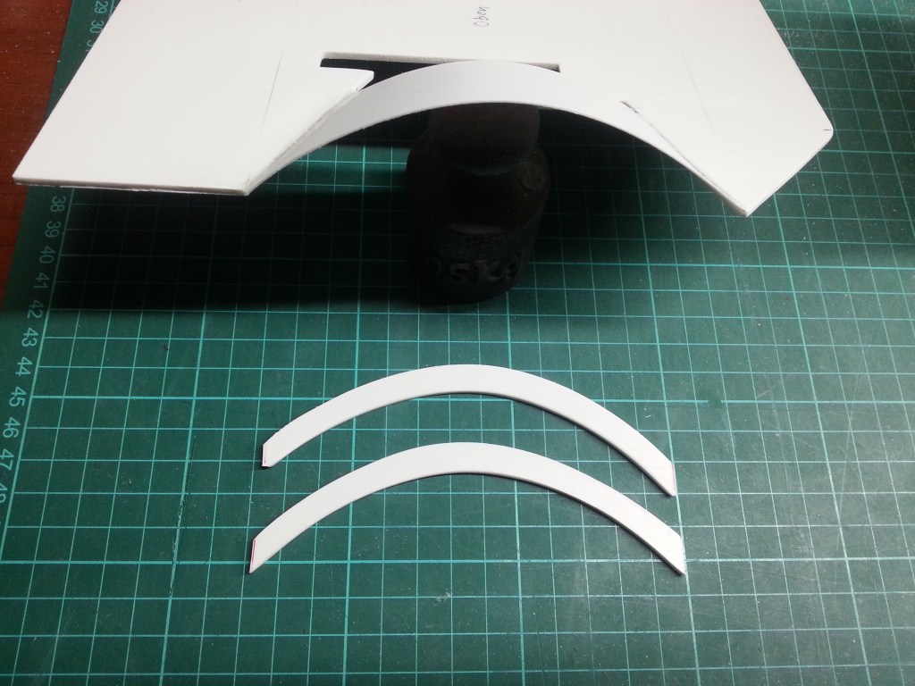
Der weitere Aufbau der Ladefläche gestaltete sich kleinteilig. In diesem Bauschritt wurden die Ladeflächenkanten und die Unterkonstruktion hergestellt. Begonnen hatte ich mit den Radkastenabschlüssen. Das sehr dünne, 1 mm starke, PS-Teil war nur bedingt verformungsstabil. Daher wurde aus 2 mm starken PS-Resten, konturenscharf ein Abschluss hergestellt. Damit lässt sich auch eine schöne Rundung herausarbeiten.
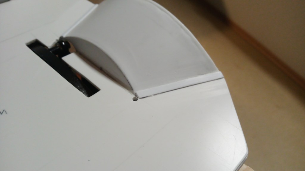
Fertig verklebt und geschliffen ist der erste Schritt geschafft.
Die Fortsetzung erfolgte am Heck der Ladefläche. Ausgehend von den Radkästen wurde ein 4-kant-Kunststoffprofil angepasst und mit der Ladeflächenunterseite verklebt.
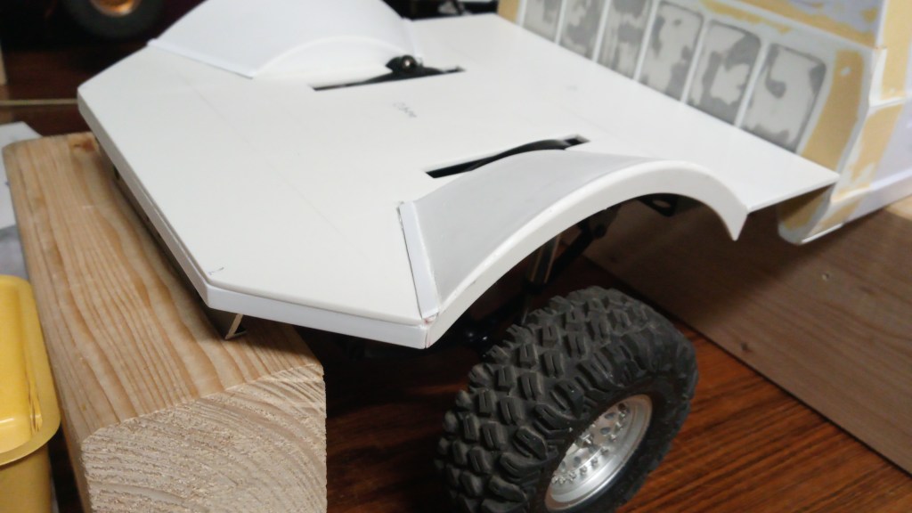
An den Übergängen der Kotflügel zur Ladefläche gab es dann noch ein Halbrundprofil zur Stablisierung der Klebestelle. An die Unterseite kommen noch weitere Profile zur finalen Verstärkung. Der Fahrbetrieb im Geländeeinsatz verzeiht schließlich keine Nachlässigkeiten. 😉
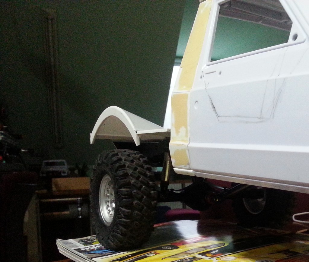
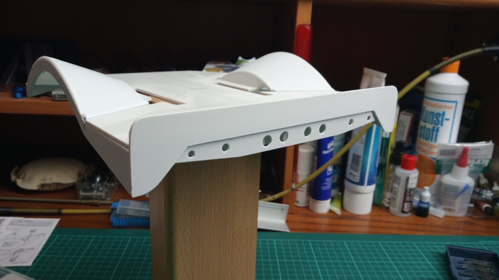
An der Stelle ein Ausblick auf das fertige Produkt. Der Kotflügel wird später mattschwarz lackiert und der Ladeflächenboden erhält eine Verkleidung aus strukturiertem Aluminiumblech.
Weiter auf der Unterseite; aus realen Vorlagen, habe ich mir gängige Unterbodenprofile als Vorbild genommen. Dort sind sowohl U-Profile als auch 4-kant-Profile, als Verstärkungselemente verbaut. Ich habe mich für U-Profile entschieden. Sie werden optisch auf die Lasten und Kräfte angepasst werden. Innen am Rahmen wird es höher sein und zum Rand hin, bis zur bereits montieren Kante, flach auslaufen. Zuerst aber der Baustand auf der Unterseite.
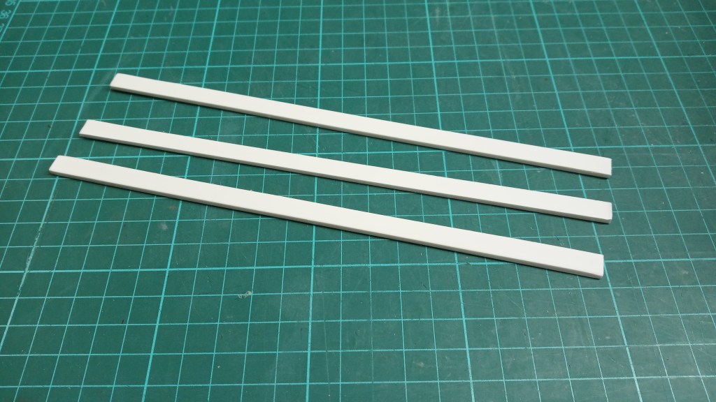
Die ersten Schritte zum Bau der Struktur. Zunächst nur drei Streifen als Basis der Profile. Material, 2,5 mm starkes Polystyrol, um für die jeweils seitlichen Stege eine ausreichende Klebefläche zu schaffen.
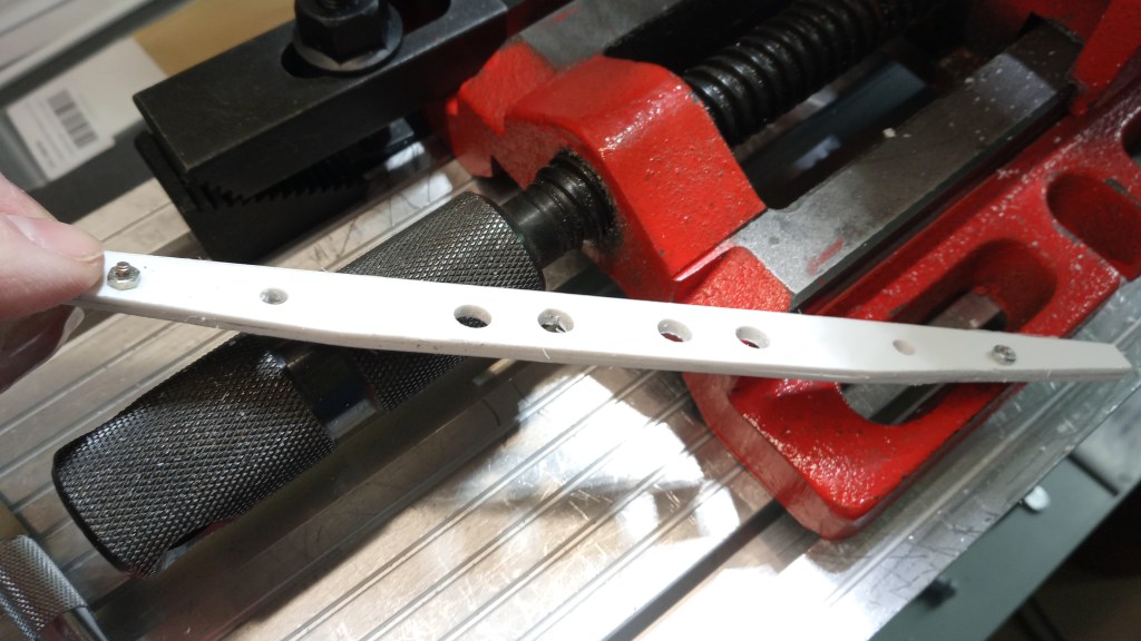
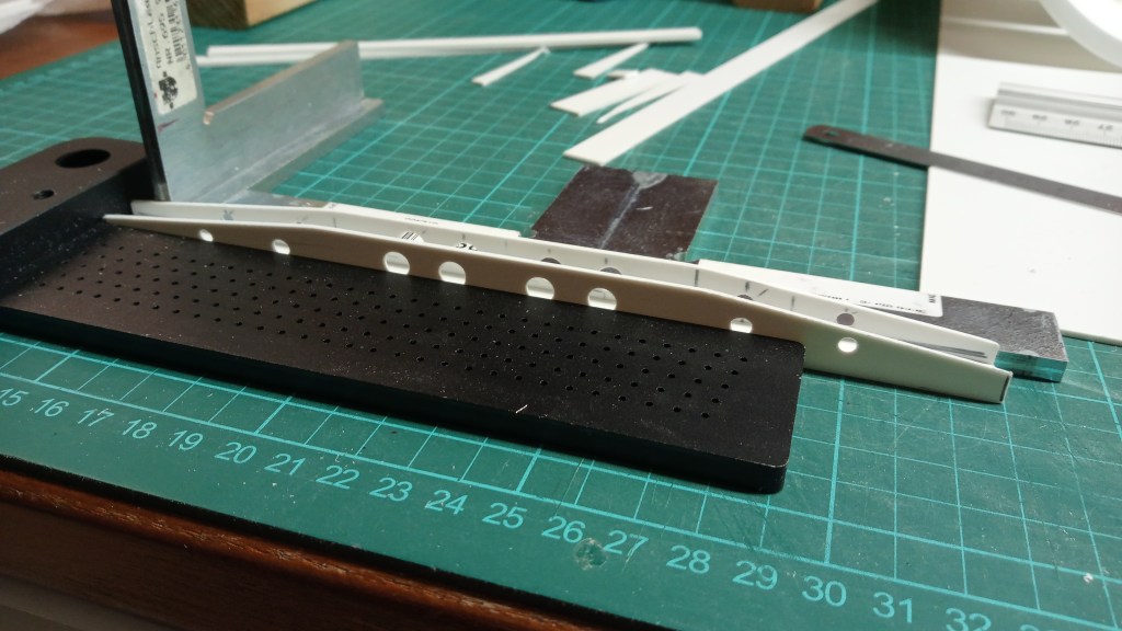
Etwas aufwändiger die beiden Seiten, hier zunächst nur der vordere Querträger. Nach dem Schneiden zuerst miteinander verschraubt und dann die restlichen Löcher gemeinsam gebohrt. Final noch schleifen und entgraten.
Als Kombination ist schon erkennbar, wohin der Weg führen soll…
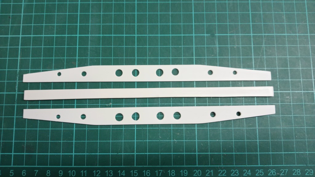
… zu einem Rahmenunterzug, um die Ladefläche zu stabilisieren!
An nachfolgender Position wurde die Traverse montiert, bzw. verklebt. Das Ganze jetzt noch mindestens zweimal. Eine vor und eine weitere hinter dem Kotflügel. Dann überprüfe ich die Steifigkeit und werde bei Bedarf nachbessern.
Um auch die Längssteifigkeit zu erhöhen, wurden vor den Kotflügeln noch seitliche Profilelemente eingepasst. Sie sind seitlich mit der vorab gebauten Traverse verklebt. Somit entsteht ein Längs- und Querverbund, im Bereich unterhalb des Überrollbügels.
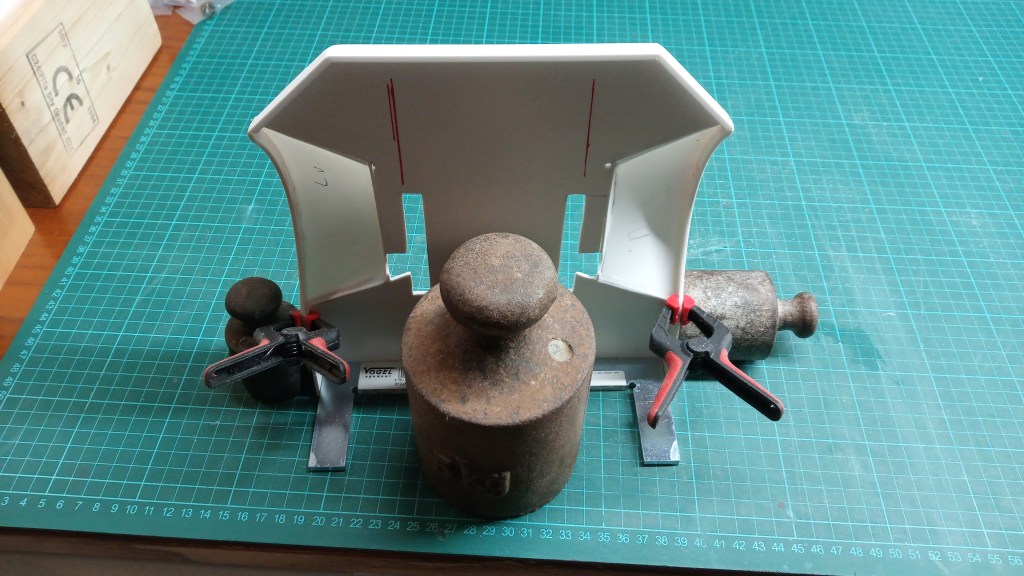
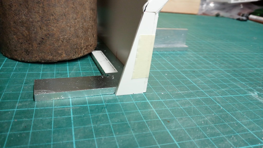
Die dabei entstandene Halte- und Spannkombination ist ein interessantes Arrangement, verschiedenster Gegenstände. Auf der Rückseite hält ein Anschlagwinkel die Ladefläche im Lot.
Etwas Aufwand zur Fixierung von zwei kleinen Teilen. Von der eingebauten Traverse wird im Endausbau aber etwas weniger zu sehen sein. Ein etwa 12 mm über die Ladefläche ragender vorderer Abschluss, verbindet alle noch sichtbaren Kanten. Um die gelochte Struktur nicht vollständig abzudecken, werde ich das Versteifungselement entsprechend aussparen. Das Ergebnis macht mich aber vorerst sehr glücklich. 😃
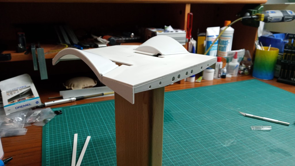
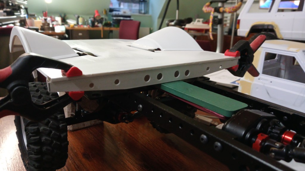
Und so sieht das jetzt im eingebauten Zustand aus.Die Quersteifigkeit ist somit vorne ausreichend. Der Überrollbügel wird das aber noch weiter erhöhen.
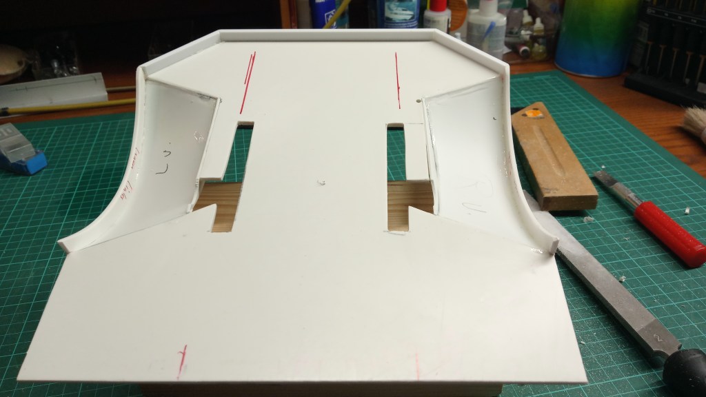
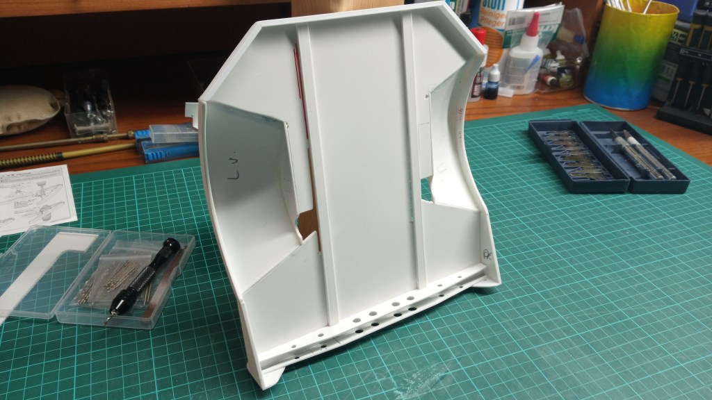
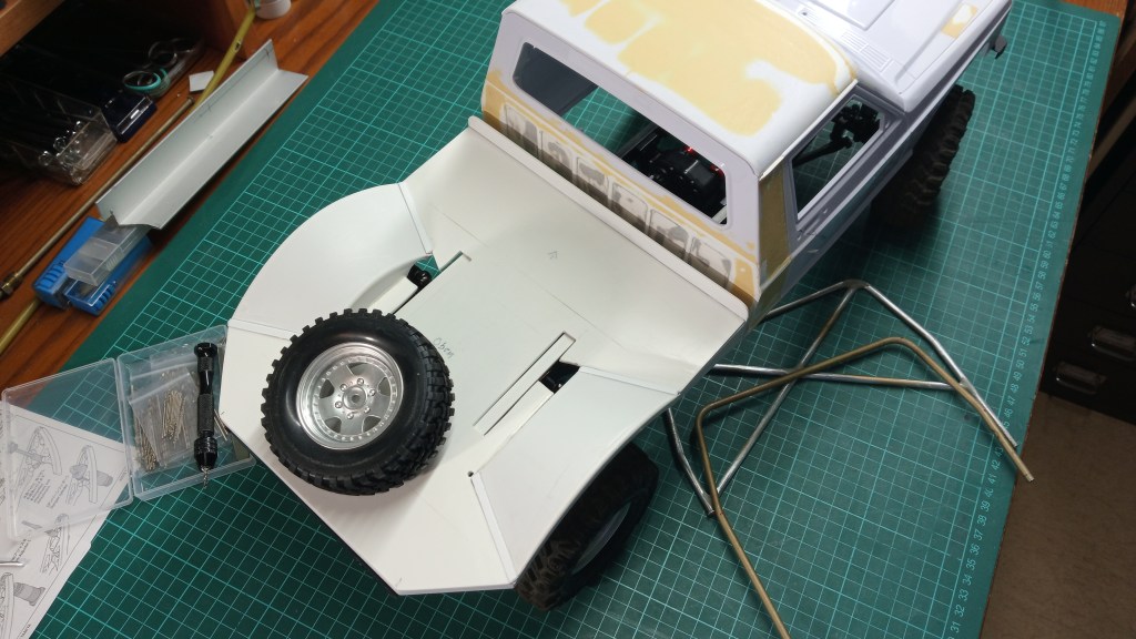
Was noch fehlt sind zwei weitere Quertraversen und ebenso zwei Längsträger im Rahmenverlauf. Im folgenden Bild habe ich die Unterteile der Längsträger schon einmal eingelegt. Wie zu sehen ist, hätte ich mir die Ausschnitte sparen können. Die Ladefläche kommt höher als zunächst vermutet. Durch meine umlaufende Randverstärkung, besonders an der Rückseite, erhöht sich die Ladeflächenebene etwas und macht die Aussparungen letztlich überflüssig. So etwas passiert eben beim Prototypenbau. 😄
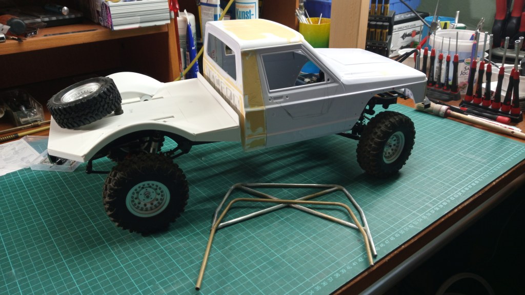
Mehr davon im nächsten Beitrag. Ich brauche ja auch für die Zukunft noch etwas zum Schreiben. Zum Abschluss noch einen Blick auf den vorläufigen Bauzustand.
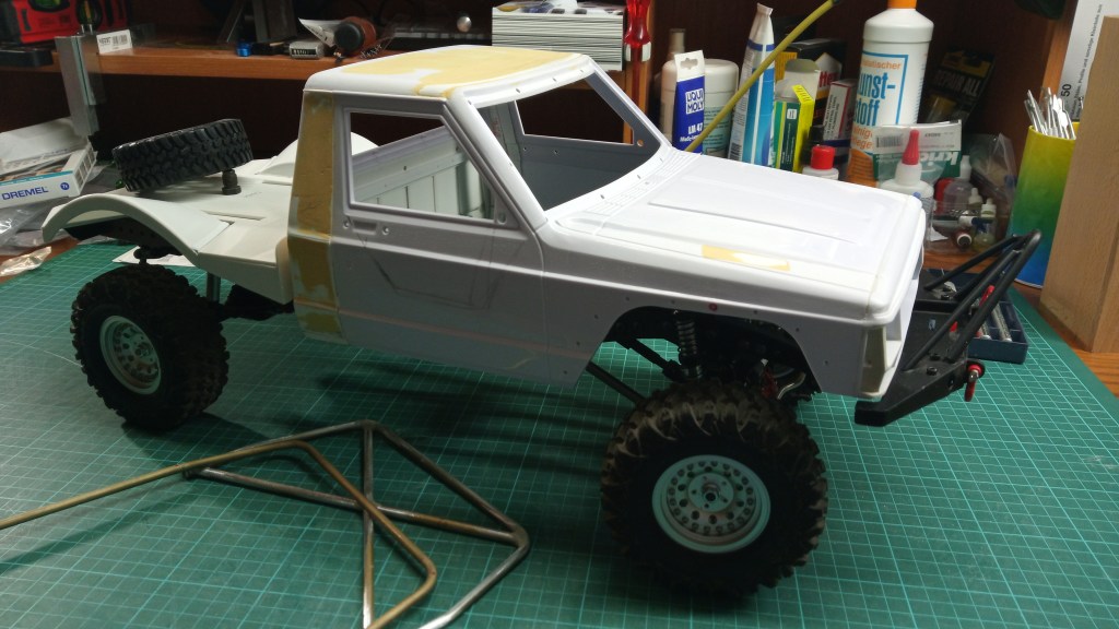
Wird schnellstmöglich fortgesetzt…
English Version
Truggy loading area details
The days are getting shorter, the cold and wet weather is not very inviting to spend time outdoors. Actually, the perfect time to tinker. At the moment, however, I’m rather sluggish and looking for my guide. The search for solutions and the building scope still lying before me dampen somewhat the building desire. Nevertheless, the joy remains when work steps succeed. I do not build after a plan, which was realized construction- and building-technically. So also the following results.
The further construction of the loading area was divided into small parts. In this step, the edges of the loading area and the substructure were built. I started with the wheel arch ends. The very thin, 1 mm thick, PS part was only conditionally stable against deformation. Therefore, I used 2 mm thick PS remnants to create a sharp contoured end. This also allows a nice rounding to be worked out.
Finished glued and sanded, the first step is done.
The continuation took place at the rear of the loading area. Starting from the wheel housings, a 4-sided plastic profile was adapted and glued to the underside of the loading area.
At the transitions of the fenders to the loading area, there was then another half-round profile to stabilize the gluing point. Further profiles were added to the underside for final reinforcement. After all, off-road driving does not forgive any negligence 😉 .
Here’s a look at the finished product. The fender will later be painted matte black and the loading area floor will receive a cladding of textured aluminum sheet.
Continuing on the underside; from real templates, I have taken common underbody profiles as a model. There are both U-profiles and square profiles, as reinforcing elements installed. I decided to use U-profiles. They will be visually adapted to the loads and forces. Inside the frame it will be higher and taper to the edge, to the already mounted edge flat. But first, the construction status on the bottom.
The first steps to build the structure. First, only three strips as the basis of the profiles. Material, 2.5 mm thick polystyrene, to create a sufficient adhesive surface for each of the lateral webs.
Somewhat more complex the two sides, here initially only the front cross member. After cutting, first screwed together and then drilled the remaining holes together. Finally sanding and deburring.
As a combination it is already recognizable where the way should lead…
… to a frame beam to stabilize the loading area!
At the following position the crossbeam was mounted, respectively glued. The whole thing now at least twice more. One in front and another one behind the fender. Then I will check the stiffness and if necessary I will improve it.
To increase the longitudinal stiffness as well, lateral profile elements were fitted in front of the fenders. They are glued to the side of the previously built crossmember. This creates a longitudinal and transverse bond in the area below the roll bar.
The resulting holding and clamping combination is an interesting arrangement of various objects. At the rear, a stop bracket keeps the loading area perpendicular.
A little effort to fix two small parts. However, a little less will be seen of the built-in crosshead in the final build. A front end protruding about 12 mm above the loading area connects all edges that are still visible. In order not to completely cover the perforated structure, I will leave out the stiffening element accordingly. However, the result makes me very happy for the time being. 😃
And this is how it looks now when installed. So the transverse stiffness is sufficient at the front. But the roll bar will increase that even more.
What is still missing are two more cross members and likewise two longitudinal members in the frame run. In the following picture I have already inserted the lower parts of the longitudinal beams. As you can see, I could have saved myself the cutouts. The loading area is higher than I first thought. Due to my circumferential edge reinforcement, especially at the rear, the loading area level increases somewhat and ultimately makes the cutouts superfluous. That’s just what happens in prototyping. 😄
More of that in the next post. I need something to write about for the future. Finally, a look at the preliminary state of construction.
Will be continued as soon as possible…
Translation, with the kind support of deepl.com
