Quellen: Internet-Bildersuche
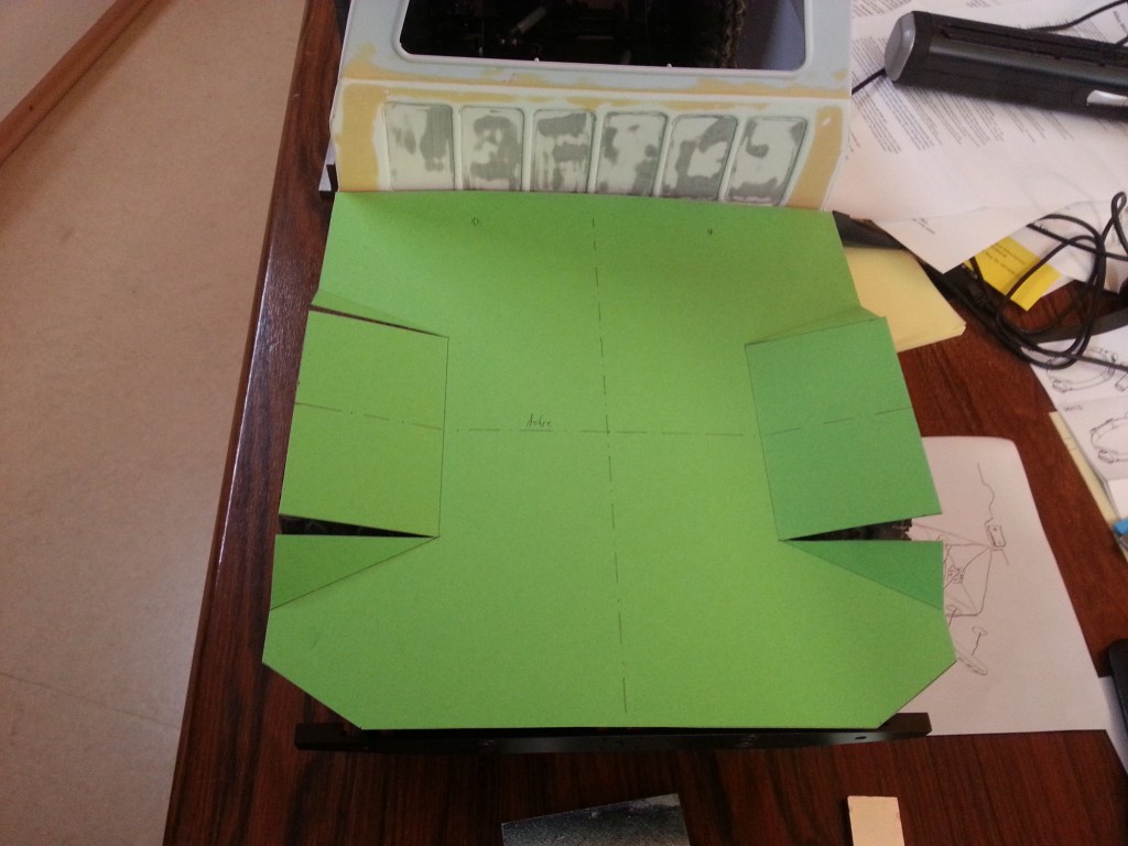
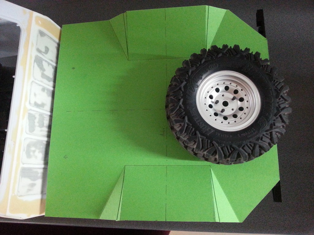
English VersionEin zartgrüner Bastelkarton aus dem Fundus meiner Frau, hat zum Comanche gefunden. Nach einer technischen Zeichnung im Maßstab 1:1 und einem unspektakulären Scherenschnitt, entstand die Vorlage für den Comanche Heckbereich. Die Radkästen wurden dabei leicht nach oben angewinkelt und ebenso die Abschlüsse des zukünftigen Kotflügels.
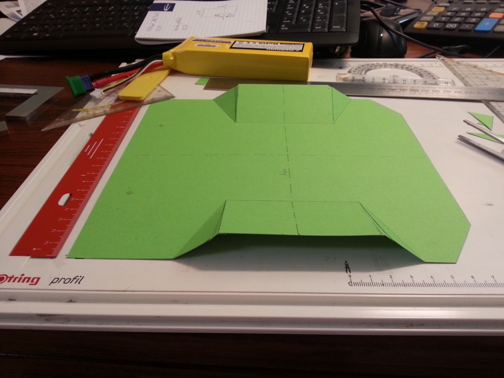
Die durch die Flächenvergrößerung und das Zuschneiden fehlenden Dreiecke, wurden noch nachträglich ausgeschnitten und eingeklebt. So entstand ein dreidimensionales Bauteil. Es dient als Vorlage für den späteren Boden. Der aufgesetzte Radkasten wird getrennt gebaut und aufgeklebt. An den Seiten wird ein Vierkant- oder Winkelprofil, einen stabilen Abschluss bilden.
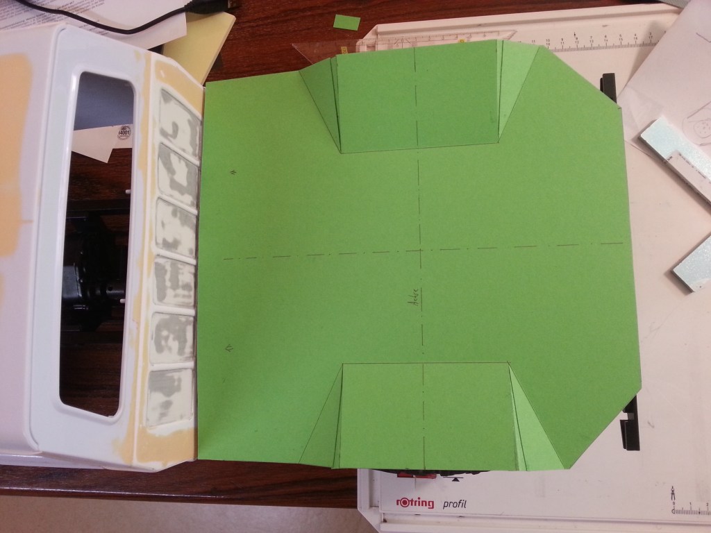
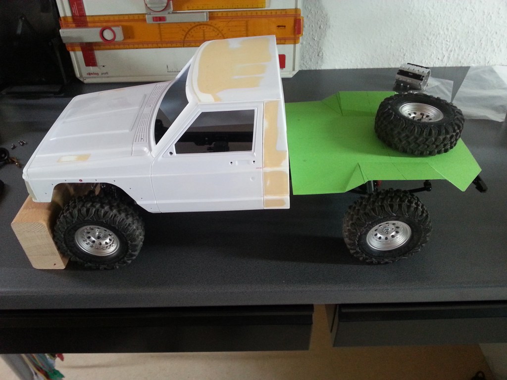
Diese Baugruppe wird auf einer Unterkonstruktion mit dem Fahrzeugrahmen verschraubt. In der Draufsicht zeigt sich die spätere Anordnung. Die beiden überstehenden Stoßstangenenden, werden am Übergang zur Baugruppe abgetrennt. Daran schliesst sich dann nahtlos, dass vorher schon beschriebene, umlaufende Randprofil an.
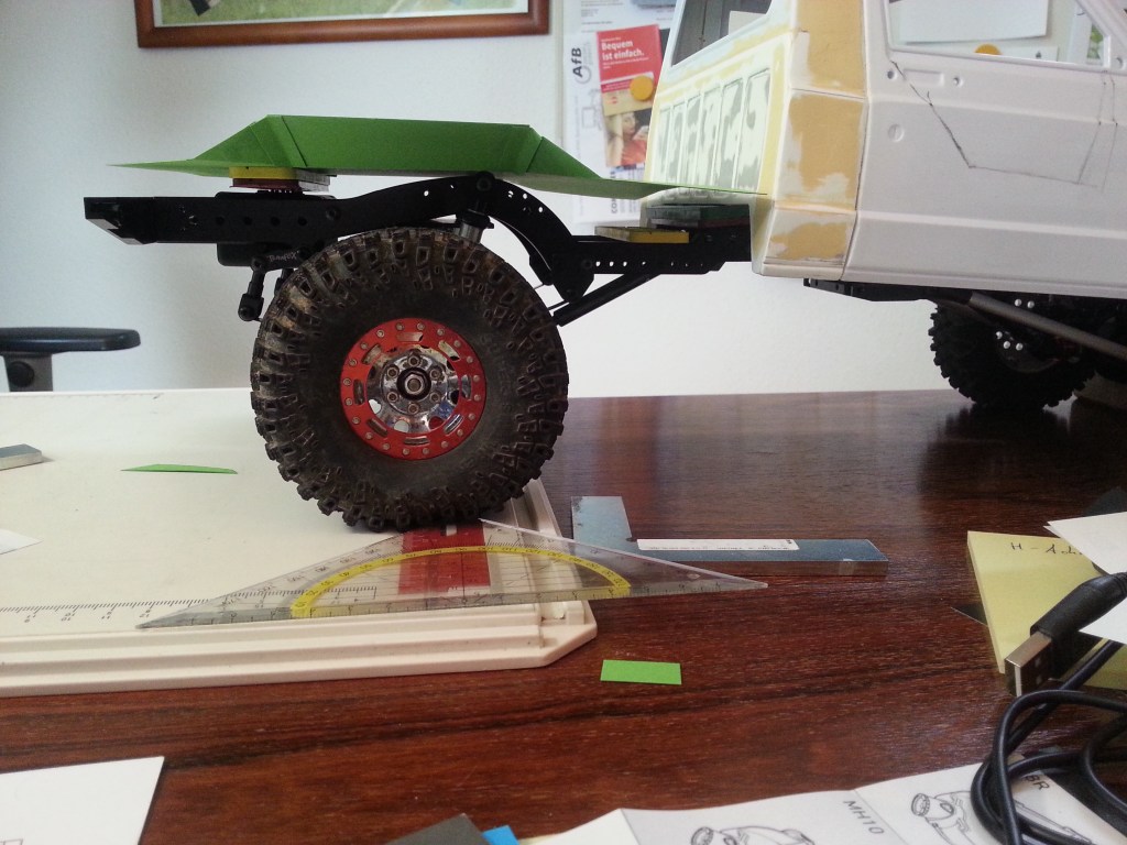
In der Seitenansicht ist die Lücke zwischen Rahmen und Ladefläche erkennbar. Am Übergang von Ladefläche und Fahrerhaus, wird ein etwas massiveres Profil, den späteren Überrollbügel aufnehmen. Seine beiden 1×1 cm großen Bodenplatten, werden mit vier Schrauben M 2,0 auf der Bodengruppe verschraubt. Die beiden nach hinten gerichteten Stütztraversen des Bügels, sind später im Bereich des Dämpferauges mit dem Unterbau verbunden. Je nach Höhe des verwendeten Akkus, ziehe ich sogar in Erwägung, die Ladefläche im Bereich der Rahmenbogens auszusparen. Darüber wird eine Werkzeugkiste montiert, um die Aussparungen zu verstecken. Durch die Absenkung soll der Schwerpunkt optimiert werden.
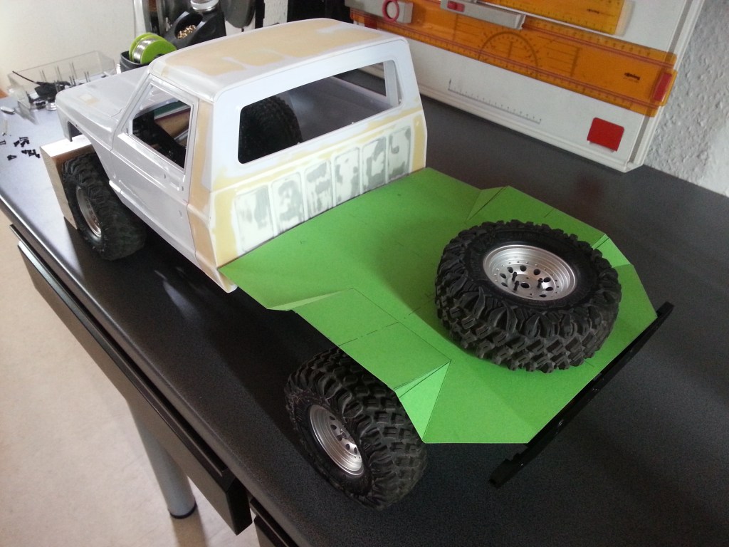
Das Reserverad bildet nach hinten den Abschluss, um auch die Gewichtsverteilung insgesamt zu optimieren.
Durch den Überstand der Stoßstange, liegt der mögliche Rampenwinkel nun bei etwa 70°. Da die Blattfeder noch weiter Richtung Fahrerhaus verschiebbar ist und vielleicht auch wird, steht eventuell noch eine Kürzung der hinteren Rahmenenden auf dem Bauplan. Allerdings muss ich auch nicht unbedingt senkrechte Rampen überqueren. Aber schön zu wissen, was noch machbar ist. An wettbewerbsoptimierten Truggys, wird der hintere Rahmen komplett abgetrennt und die Achse soweit wie technisch möglich, Richtung Fahrerhaus montiert. Das alles ist an einem Hilfsrahmen befestigt. Effizient, aber so sieht es für mich nicht mehr wirklich nach Auto aus.

Zum Abschluss der Baustand in der Gesamtansicht.
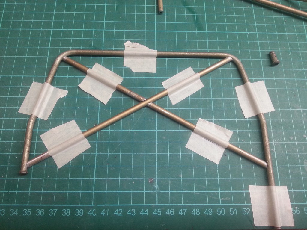
Kurz vor meinen Kaffeepäuschen, indem der Beitrag veröffentlicht wird, habe ich noch zwei Stunden Arbeit eingeschoben. Das Ergebnis ist der Hauptbügel hinter dem Fahrerhaus.
Als nächsten Schritt geht es an die Materialbeschaffung und die Produktion der weiteren Metall-Bauteile. Viel aufwändige und kleinteilige Arbeit liegt jetzt vor mir. Ich werde in Kürze vom weiteren Verlauf berichten.
Im nächsten Beitrag berichte ich aber zuerst vom aktuellen Baustand des SCX10 Fahrgestells. Einem kurzfristigen Karosseriewechsel und seinen dadurch neu entstandenen Problemen.
Wird schnellstmöglich fortgesetzt…
English Version
The truggy rear end under construction
Sources: Internet image search
A pale green carton from the fundus of my wife has found its way to the Comanche. After a technical drawing on a scale of 1:1 and an unspectacular silhouette, the template for the Comanche rear section was created. The wheel housings were slightly angled upwards and also the ends of the future fender.
The missing triangles due to the enlargement of the area and cutting were cut out and glued in afterwards. The result was a three-dimensional component. It serves as a template for the later floor. The attached wheel arch is built separately and glued on. On the sides a square or angle profile will form a stable conclusion.
This assembly is bolted to the vehicle frame on a substructure. The top view shows the later arrangement. The two protruding bumper ends are cut off at the transition to the assembly. This is followed seamlessly by the previously described circumferential edge profile.
In the side view the gap between frame and loading area is visible. At the transition between the loading area and the driver’s cab, a somewhat more massive profile, the later roll bar, will accommodate. Its two 1×1 cm large base plates are bolted to the floor assembly with four M 2.0 screws. The two rear-facing support cross members of the roll bar are later connected to the substructure in the area of the shock absorber eye. Depending on the height of the used battery, I even consider to leave out the loading area in the area of the frame bows. A toolbox will be mounted above it to hide the recesses. By lowering it, the center of gravity should be optimized.
The spare wheel finishes off the rear of the vehicle to optimize the overall weight distribution.
Due to the overhang of the bumper, the possible ramp angle is now about 70°. Since the leaf spring can be moved further towards the cab, and maybe will be, there might be a shortening of the rear frame ends on the construction plan. But I don’t have to cross vertical ramps either. But it’s nice to know what else is possible. On competition-optimized truggies, the rear frame is completely cut off and the axle is mounted towards the cab as far as technically possible. All this is attached to a subframe. Efficient, but for me it doesn’t really look like a car anymore.
At the end of the construction stage in the general view.
Shortly before my coffee break, when the article will be published, I put in another two hours of work. The result is the main bar behind the cab.
The next step is the procurement of materials and the production of the other metal components. A lot of complex and small work is now ahead of me. I will report on the further progress shortly.
But in the next article I will first report on the current state of the SCX10 chassis. A short-term body change and its new problems.
Will be continued as soon as possible…
Translation, with the kind support of deepl.com
