Quellen: Internet Bildersuche
English Version
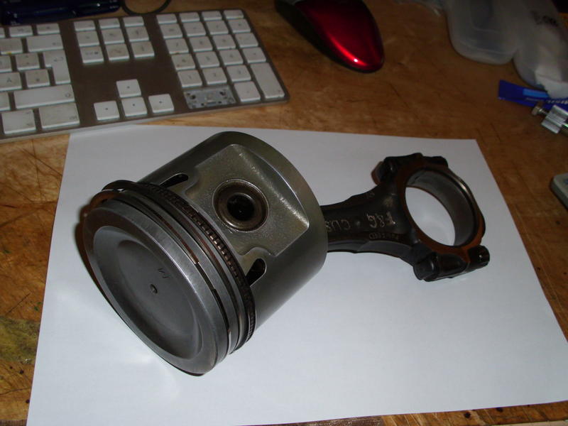
Der Rat Comanche soll möglichst improvisiert aussehen. Zur verbrauchten Optik kommt auch der Bedarf alles Verfügbare, in eine brauchbare Form umzuwandeln. Kreativität ist dabei gefordert. Für Rückfahrscheinwerfer und Außenspiegel hatte ich mir daher etwas Ausgefallenes als Halterung überlegt. Hier will ich einmal näher vorstellen, wie ein solcher Kolben aus Kunststoff gebaut werden könnte. Könnte daher, weil ein 3-D-Drucker das natürlich noch perfekter schaffen würde. Mir geht es aber in erster Linie darum, möglichst viel selbst herzustellen. Das macht großen Spaß und wenn es auch noch gelingt, erfreut es mich umso mehr. Zunächst also ein Bild, dass mir als grobe Vorlage diente.
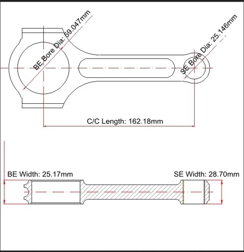
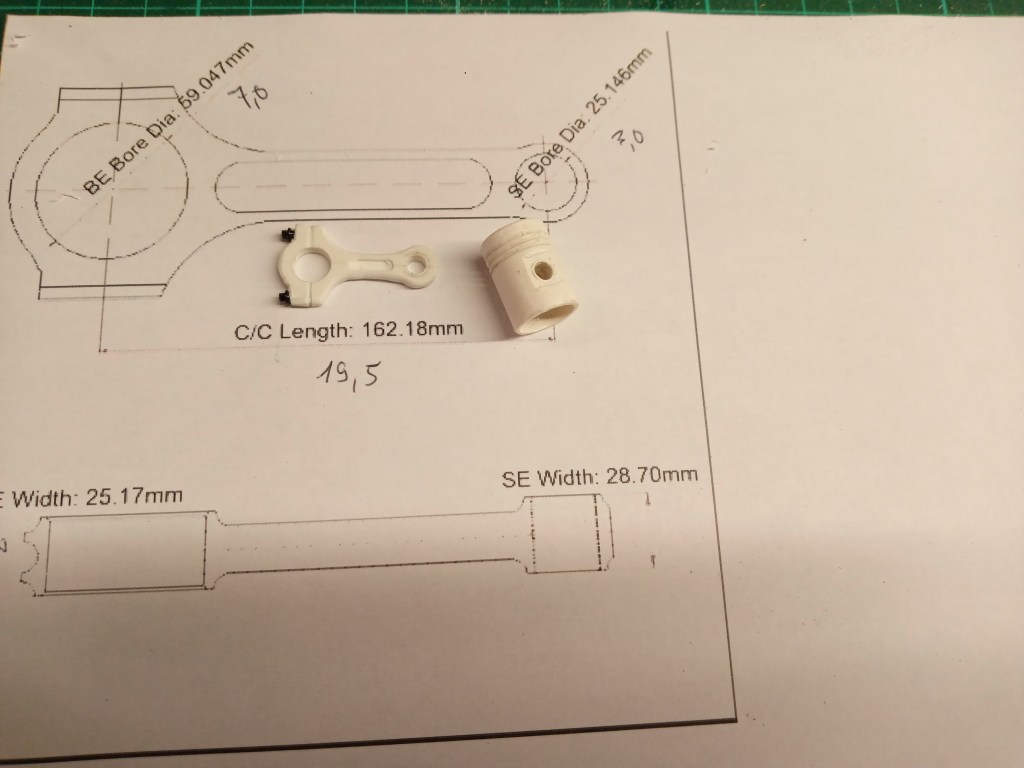
Für das Pleuel gab es auch eine wunderbare Vorlage. Danke Internet!
Zum Bau des Kolbens habe ich mich am Maßstab des Rat Comanche orientiert, der bei 1:8,3 liegt. Kunststoffrohre im Außendurchmesser 10, 12 und 14 mm wurden verwendet. Durch die Wandstärke von 1 mm, passen die Rohre auch jeweils ineinander. Produktionstechnisch kommt es dabei zu minimalen Größendifferenzen, die aber bei Bedarf durch leichtes Schleifen mit Schmirgelpapier korrigiert werden können.

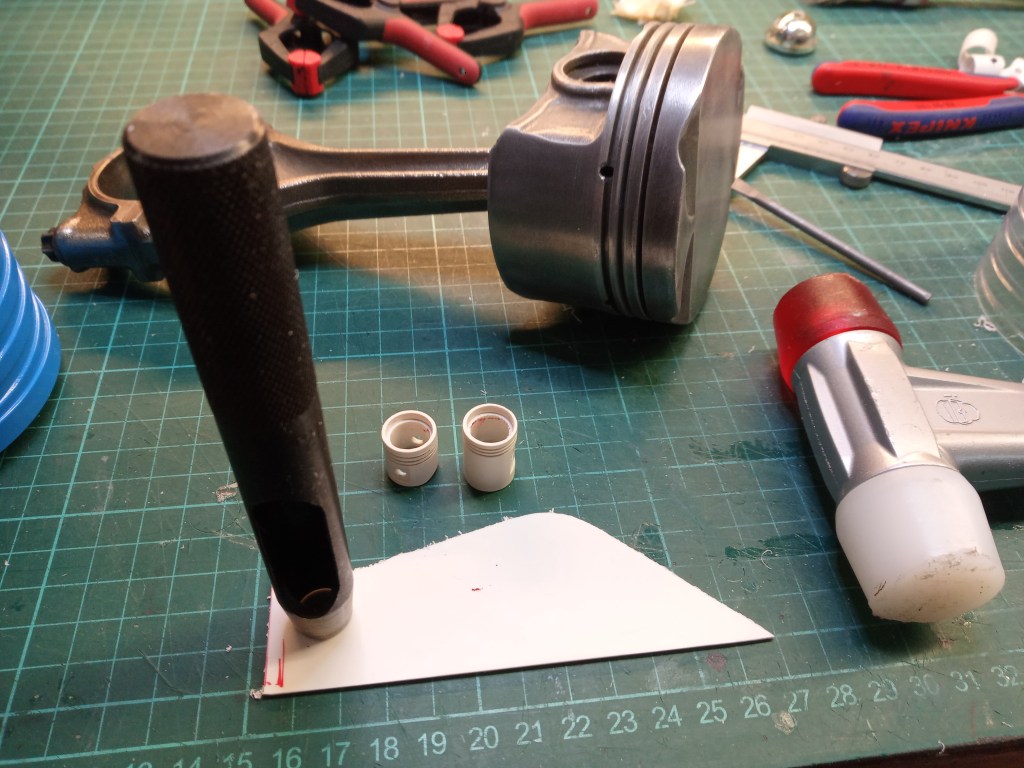
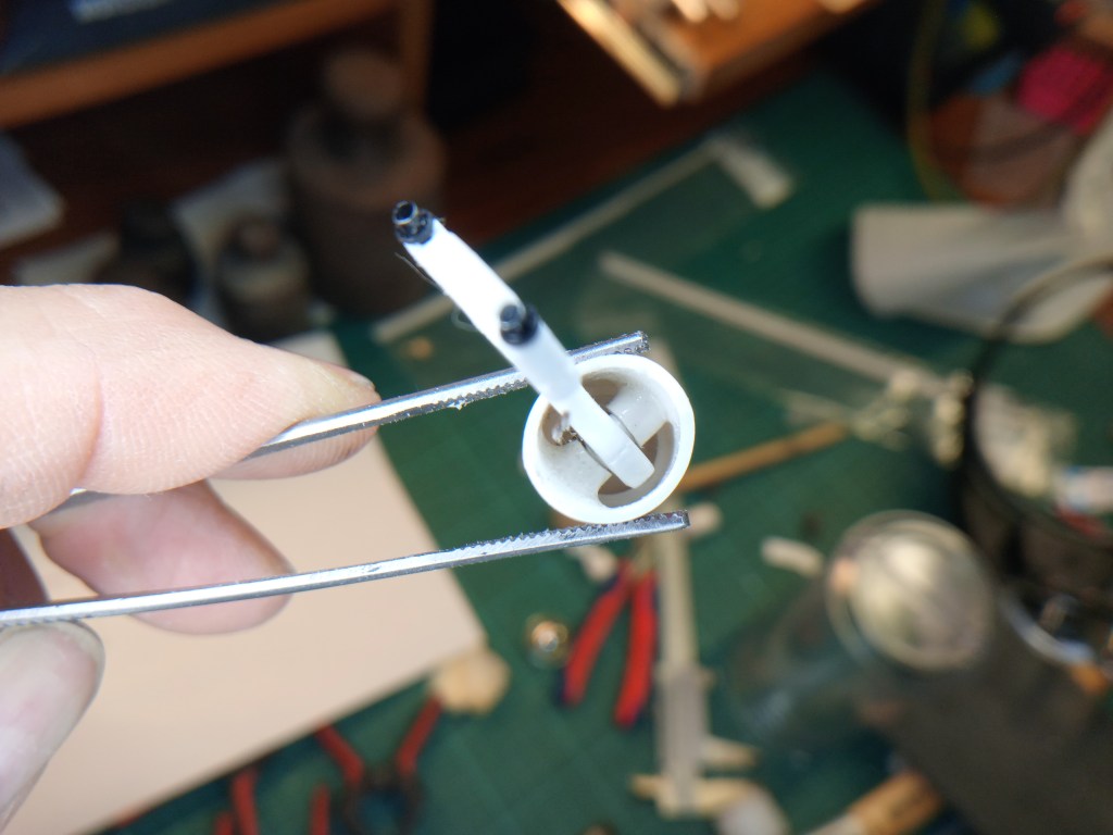
Zum Bau hatte ich die Rohre mit einer Säge gekürzt. 25 mm Länge hatten meine Rohrstücke nach dem Sägen. Noch zu lang, aber um es bei der noch folgenden Bearbeitung auch handhaben zu können, eben mit einem Zuschlag. In das Außenrohr von 14 mm kam ein Innenrohr 12 mm, ca. 12 mm lang. Es wurde so weit eingeschoben, dass am Kolbenboden ein Versatz von ca. 1,2 mm vorliegt. Hier ein Bild aus einem fortgeschrittenen Bauabschnitt, aus dem dieser Versatz erkennbar ist. Darin liegt später der Kolbenboden. Auf dem Foto rechts daneben zu sehen.

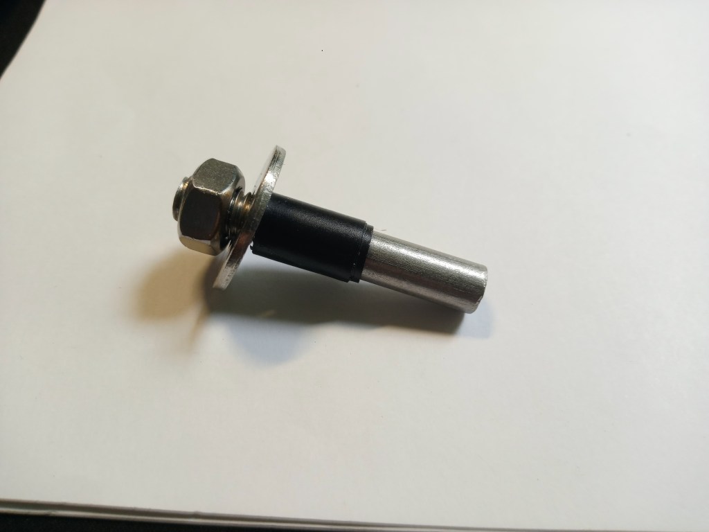
Für den nächsten Bauabschnitt ist diese Aufdopplung auch von großer Bedeutung. Die Wandstärke beträgt ja nur 1 mm. Eine 8 mm Schrauben mit gewindelosem Schaft wurde abgesägt. Klebeband darauf so dick aufgewickelt, dass der Innendurchmesser des Kolbens saugend aufgeschoben werden kann. Eine Scheibe mit Mutter sichert die Hülse auf dem Bolzen. So ist ein einigermaßen, sauberer Rundlauf sichergestellt.
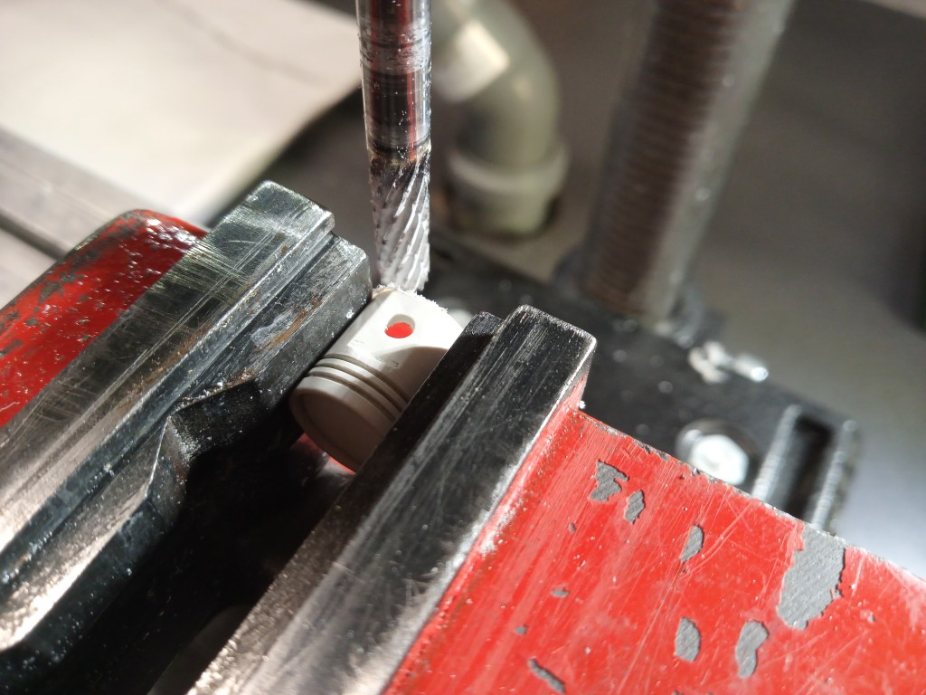
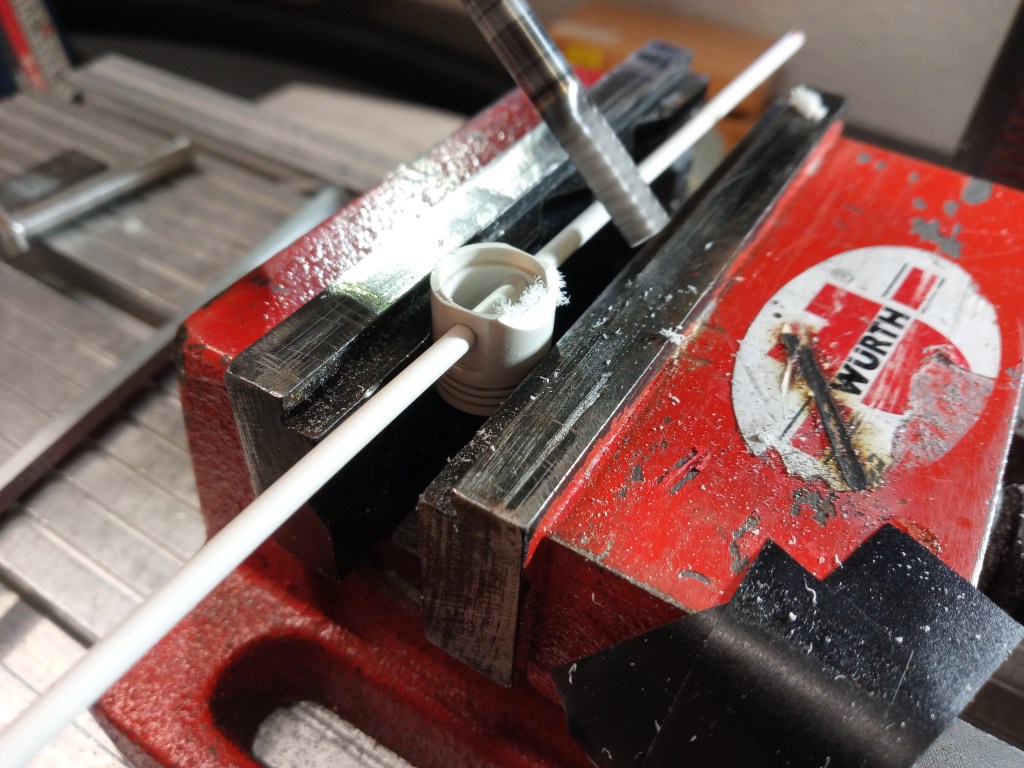
Wie im nachfolgenden Bild zu sehen ist, wurde eine kleine Handsäge mit feinem Sägeblatt, in den Maschinenschraubstock gespannt. Bei laufender Bohrmaschine, meinem Drehbank-Ersatz, wurde auf dem Koordinatentisch, die Säge in das rotierende Kunststoffrohr geschoben. Das mit größtem Feingefühl, bis eine feine Rille ausgesägt ist. Präzise nebeneinander angeordnet, ergeben sich die Nuten, der später dort sitzenden Kolbenringe. Dabei sind natürlich nach Belieben Variationen der Abstände und auch der Sägeblattstärke möglich. Der obere Ölabstreifring ist oft etwas breiter und hat auch etwas Abstand zu den weiteren Kolbenringen. Ich habe mich für eine Größe und gleichmäßige Abstände entschieden.

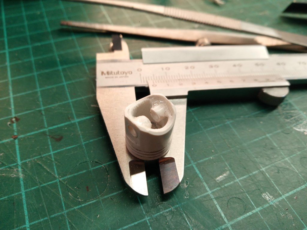
Nachdem anschließend die Bohrungen für den Kolbenbolzen gebohrt waren, wurde ein Bereich des Kolbenhemdes abgefräst. Für meine Ausführung habe ich eine 4 mm Bohrungen gesetzt. Dahinein kommt später noch ein 4 mm Kunststoffrohr.
Vorangegangen war die Herstellung des Kolbenbodens. Das habe ich mit einem Locheisen und einem Rest von 1 mm starken Kunststoffresten bewerkstelligt. In meinem Fall musste ich mit Schleifvlies die leicht differierenden Durchmesser anpassen. Nur so kann später der Kolben zum Fräsen verformungsfrei in den Schraubstock gespannt werden. Siehe vorheriges Bild.
Mit einer Skalpellklinge habe ich die scharfe Fräskante realistisch abgeschrägt. So sah das dann an einer Kolbenvariante aus.
Das Kolbenhemd ist ja oft auch noch etwas verkürzt, um die rotierende Masse zu verkleinern. Dazu wurde der Kolben, in das Prisma des Schraubstocks, hochkant eingespannt. Unter einem Winkel von 45° habe ich dann das Kolbenhemd abgefräst. Ein durchgesteckter Kunststoffstab sorgte dabei für optische Parallelität.
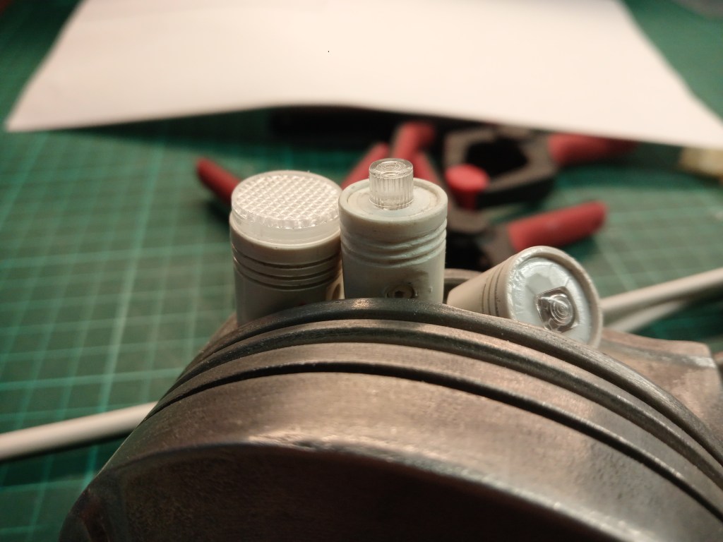
Vorab hatte ich noch die endgültige Länge des Kolbenhemdes abgefräst, liegend im Prisma. Das Ergebnis meiner Arbeit nachfolgend im Bild; die Versionen 3 und 4.

Zum Schluss noch eine Verfeinerung der Kolbenattrappe. Ein abgesägtes Kunststoffrohr 4 mm, wurde in die Bohrung des Kolbenbolzens eingeklebt.
Das nach Trocknung wieder teilweise ausgefräst wurde, führten zu dem Ergebnis. Ein Kolben mit Pleuel. Eingeschraubte, kleine Modellschrauben mit Sechskantkopf in M 1,6, ergaben ein fast realistisches Bild.
Auf die Beschreibung der Pleuel-Herstellung verzichte ich an der Stelle. Aus dem Bild ist zu sehen was gebaut wurde. Ein Kunststoffstreifen 3 mm stark, zwei Bohrungen, eine Ausfräsung je Seite und einige Feilenstriche schaffen die Pleueloptik.
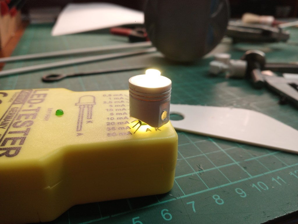
Zum Abschluss die zur Wahl stehenden Varianten für den Rückfahrscheinwerfer. Einmal ohne und einmal mit Beleuchtung. Nun grübele ich, welche Kerze später nach hinten strahlen darf… 🤔


Wird schnellstmöglich fortgesetzt…
English Version
How to build a piston in model scale
Sources: Internet picture search
The Rat Comanche should look as improvised as possible. In addition to the used look, there is also the need to convert everything available into a usable form. Creativity is required. I therefore came up with something unusual as a mount for the reversing lights and wing mirrors. Here I would like to show you in more detail how such a plastic piston could be built. Could, because a 3D printer would, of course, make it even more perfect. But my main aim is to make as much as possible myself. It’s great fun and if it works, it makes me even happier. So let’s start with a picture that served as a rough template.
There was also a wonderful template for the connecting rod. Thanks to the Internet!
To build the piston, I used the scale of the Rat Comanche, which is 1:8.3. Plastic tubes with outer diameters of 10, 12 and 14 mm were used. Due to the wall thickness of 1 mm, the tubes fit into each other. In terms of production, there are minimal differences in size, but these can be corrected if necessary by lightly sanding with sandpaper.
I shortened the tubes with a saw for construction. My pipe pieces were 25 mm long after sawing. Still too long, but in order to be able to handle it during the subsequent processing, I added an allowance. A 12 mm inner tube, approx. 12 mm long, was inserted into the 14 mm outer tube. It was pushed in so far that there was an offset of approx. 1.2 mm at the piston crown. Here is a picture from an advanced stage of construction showing this offset. This is where the piston crown will later lie. This can be seen in the photo to the right.
This doubling is also of great importance for the next construction stage. The wall thickness is only 1 mm. An 8 mm screw with a threadless shaft was sawn off. Adhesive tape was wound onto it so thickly that the inner diameter of the piston can be pushed on with suction. A washer with nut secures the sleeve on the bolt. This ensures a reasonably clean concentricity.
As can be seen in the following picture, a small handsaw with a fine saw blade was clamped in the machine vice. With the drill running, my replacement for a lathe, the saw was pushed into the rotating plastic tube on the coordinate table. This is done with the utmost sensitivity until a fine groove is sawn out. Precisely arranged next to each other, the grooves are created for the piston rings that will later sit there. Of course, the spacing and saw blade thickness can be varied as required. The upper oil scraper ring is often slightly wider and also has some distance to the other piston rings. I opted for one size and even spacing.
Once the holes for the piston pin had been drilled, an area of the piston skirt was milled off. For my version, I drilled a 4 mm hole. A 4 mm plastic tube will be inserted into this later.
This was preceded by the production of the piston crown. I did this with a punch and a scrap of 1 mm thick plastic. In my case, I had to adjust the slightly different diameters with abrasive fleece. This is the only way the piston can be clamped in the vice for milling without deformation. See previous picture.
I used a scalpel blade to realistically bevel the sharp milling edge. This is what it looked like on a piston version.
The piston skirt is often shortened slightly to reduce the rotating mass. For this purpose, the piston was clamped upright in the prism of the vice. I then milled off the piston skirt at an angle of 45°. A plastic rod inserted through it ensured visual parallelism.
Beforehand, I had milled off the final length of the piston skirt, lying in the prism. The result of my work is shown below in the picture; versions 3 and 4.
Finally, a refinement of the dummy piston. A 4 mm plastic tube was sawn off and glued into the bore of the piston pin.
This was partially milled out again after drying, leading to the result. A piston with connecting rod. Small model screws with hexagonal heads in M 1.6 were screwed in to create an almost realistic picture.
I will refrain from describing the production of the connecting rod at this point. The picture shows what was built. A 3 mm thick plastic strip, two holes, one cut-out on each side and a few file strokes create the connecting rod look.
Finally, the available variants for the reversing light. One without and one with lighting. Now I’m pondering which candle should shine to the rear later… 🤔
Will be continued as soon as possible…
Translation, with the kind support of deepl.com

wow!! 106Wie einen Kolben im Modell-Maßstab bauen
LikeLike
Grazie, questo mi rende molto felice. Spero di aver riconosciuto correttamente la lingua.
LikeLike
Thank you, I am very happy about that.
LikeLike