Quellen: RC4WD, Wikipedia, RC-HP Modellbaushop
English Version
Es ist lange her, mit einem Beitrag zum Thema Modellbau. Nun hat es mich aber wieder gepackt und ich werde wieder loslegen. Zwischendurch werde ich aber immer wieder einmal zu meinen häuslichen Baustellen ausweichen müssen.
Vor einigen Monaten hatte im Rockcrawler-Forum, ein geschätzter österreichischer Modellbauer, Bilder seines Modells eingestellt. Dabei war im Hintergrund, dass noch unfertige Fahrerhaus eines Tamiya Jeep Wrangler YJ abgebildet. Meine Anfrage zur Zukunft dieses Fahrerhauses, endete mit einem umgehenden Besitzerwechsel. Von diesem Zeitpunkt an, gab es in meinem Fundus auch ein Modell mit kurzem Radstand. Viele bildschöne Teile, vom Chrom-Kühlergrill, Cockpit, wie auch die kompletten Original-Bausatzscheinwerfer, waren mit im Packet. Dazu Metall-Dekore, lasergeschnitten Metallscharniere, die eben zu anspruchsvollem Modellbau gehören. Da kennt auch mein Forumskollege keine Grenzen, Hauptsache die Optik ist perfekt. Das Fahrerhaus wurde auch schon von ihm an einigen Stellen modifiziert. So wurde u.a. die Radläufe, Heck und Frontpartie von Teilen befreit. Als Besonderheit ist sogar ein später hinter dem Nummernschild versteckter Tankstutzen eingebaut worden. Das zunächst zur Vorgeschichte des neuen Modells. Darauf gehe ich aber heute nicht direkt ein. Bilder folgen in zukünftigen Beiträgen. Kurz und gut, das Auto brauchte noch ein Fahrgestell und das gab es bisher noch nicht. Ein Gutschein in nennenswerter Größenordnung half mir aber bei diesem Luxusproblem. 😏
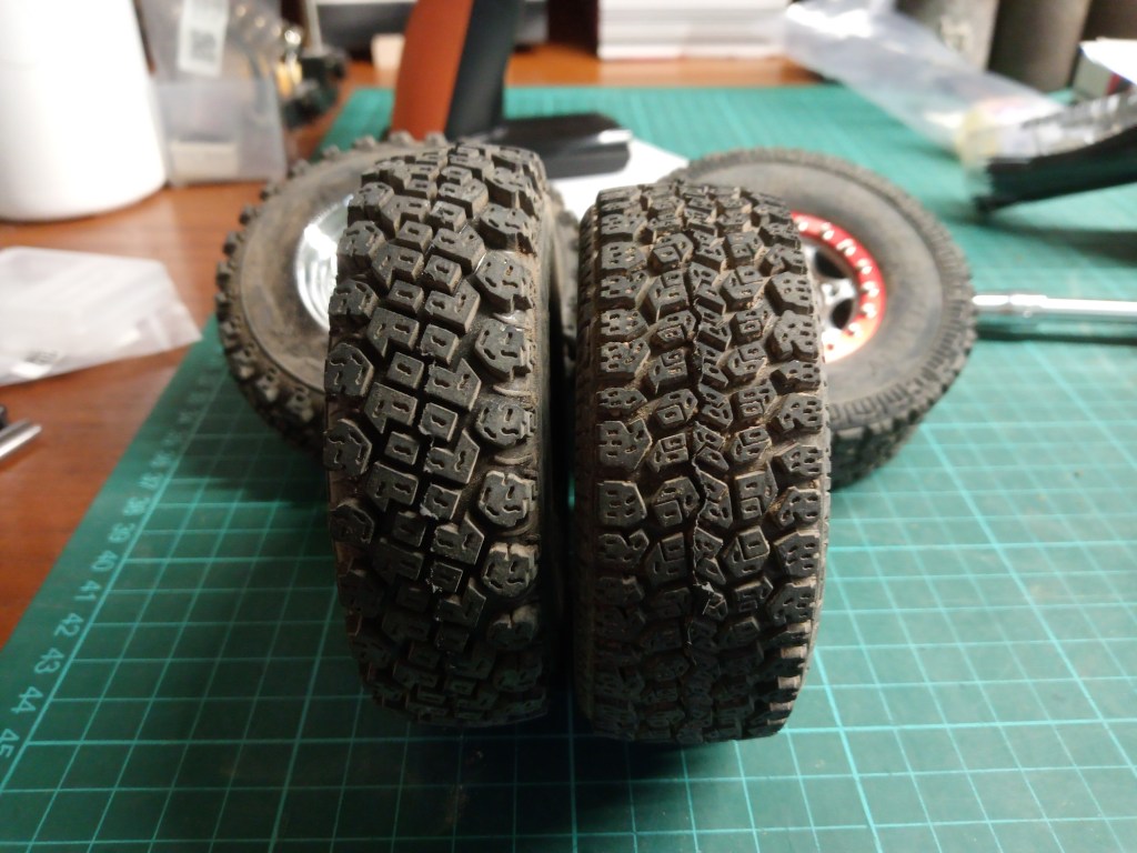
Auf den Bau des Fahrgestells gehe ich nicht näher ein. Hunderte solcher Fahrgestelle sind schon dokumentiert worden. Ein aber insgesamt souveräner, passgenau und robust aufgebauter Bausatz. Allerdings auch mit Defiziten. So sind die die Bausatz-Achsen bei der Modellvariante CFX nicht kugelgelagert, enthalten sind nur Messingbuchsen. Alle Fahrwerksstreben sind in Kunststoff gefertigt, die allerdings für drei verschiedene Radstände. Achsabstände von 242, 252 und 267 mm sind mit diesem Fahrgestell so realisierbar. Eine hintere Stoßstange ist nicht vorhanden, die vordere aus Kunststoff. Als weitere Einschränkung sind auch die Dämpfer aus Kunststoff und letztlich gibt es noch zwar ansehnliche, aber leider nur aus Kunststoff gefertigte Felgen in Stahloptik. Schwere Räder sind aber für ein möglichst perfektes Fahrbild eine wichtige Voraussetzung. Für den Kaufpreis unter 200€ erhält man aber dennoch ein hochwertiges Modell, das Anfängern einen guten Start ermöglicht. Modellbauleidenschaft fängt aber da erst an und der Anschaffungswert hat sich bei der ersten Tuningstufe gleich einmal verdoppelt. Ein Kugellagersatz, Alu-Links und Alu-Stoßdämpfer, sowie eine Halterung für die Servomontage im Rahmen unterhalb des Motors, der auch gekauft werden muss, sind dafür verantwortlich. Aber kein Grund zur Trauer, ganz im Gegenteil. Team Raffee Dämpfer, mit Silikonöl und Spezialfett geschmiert und schwere Aluräder wurden so montiert. Bei den Felgen war und bin ich noch immer etwas unschlüssig. Zwei Radsätze standen für die Abstimmungsfahrten zur Verfügung. Vorne montiert, RC4WD Walker Evans Legend 501 in der Größe 1.7 Zoll und hinten die klassische Felgenoptik vieler Geländewagen. In verchromter und schwarzer Ausführung, 1.9 Zoll groß.

Allererste Fahrversuche mit den Bausatzrädern auf den Chromfelgen, beides in 1.9 Zoll wurden vorzeitig beendet. Wenig bis gar keine Traktion, war keine Grundlage für weitere Fahrtests. Also wieder suchen und neu bestellen. Die Auswahl an 1.7 Zoll-Reifen ist sehr übersichtlich. Da der Außendurchmesser deutlich unter 100 mm bleiben musste, fiel die Wahl auf sehr weiche Dick Cepek Trail Country von RC4WD. Ich kann es vorwegnehmen, ein sehr guter Reifen auf trockenem und steinigem Untergrund. Optisch zudem eine Augenweide.
Schließlich noch die Chromfelgen, für die ich RC4WD Dick Cepek F-C II Gummis ausgewählt hatte. Sie sind geringfügig größer im Außenmaß aber auch schmäler als die Trail Country. Auch dieser Reifen erzielte auf meinem aktuellen Gartenparcours ein mehr als befriedigendes Ergebnis. Traktionstechnisch und auch im Hinblick auf die Proportionen ist der 1.7 Zoll Radsatz der Favorit. Wäre da nicht das gesteckte Ziel eines Jeeps in klassischer Edeloptik. Eine gedeckte Lackierung und viel kontrastierende silberne und chromglänzende Anbauteile sehe ich vor meinem Auge. Das schreit doch geradezu nach Chromfelgen!?
So viel zunächst von meinen ersten Gedanken, der Geschichte des Wrangler und nun wie gewohnt, wieder Technik im Detail. Ich beginne einmal mit den Änderungen am Fahrwerk selbst. Zur Wiederholung, alle Messingbuchsen in den Achslagern wurden gegen Kugellager getauscht. Das Verteilergetriebe und das Hauptgetriebe sind schon im Bausatz kugelgelagert. Die Fahrwerksstreben sind durch ein MST-Tuningkit für 242 mm Radstand aufgewertet worden. Dabei habe ich die vorderen Links gleich um 5 mm verlängert, was den Radstand auf optisch gefälligere 245 mm vergrößert. Das Vorderrad steht somit zentrierter im Radkasten.
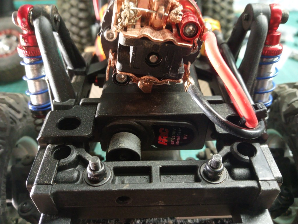
Im Bausatz ist die Montage des Lenkungsservos auf der Vorderachse vorgesehen. Das wollte ich aber nicht, wenn es auch nicht nur Nachteile für diesen Montageplatz gibt. Das Eigenlenkverhalten beim Einfedern ist so ein Beispiel. Da ich aber beim Geländefahren ständig am Ein- und Gegenlenken bin, ist das zu vernachlässigen, aber dennoch vorhanden. Durch die Montage des Lenkservos auf der Achse, verändern sich beim Ein- und Ausfedern, die Abstände vom Lenkhebel zum Servohorn nahezu nicht. Ist das Servo hingegen am Rahmen angeschraubt, werden beim Einfedern links vorne auch die Räder geringfügig nach links ausgelenkt. Ein Panhardstab könnte diesen Effekt verringern, die Arbeit mache ich mir aber dieses Mal nicht. Ich werde einfach stärker gegenlenken… 😊
Auf dem Foto auch der neuangeschaffte 20T Motor von Ruddog mit 5 Wicklungen. Ein Traum für einen drehmomentstarken Langsamläufer mit Schleifkontakten. Komplett revidierbar und das alles für unter 30€!
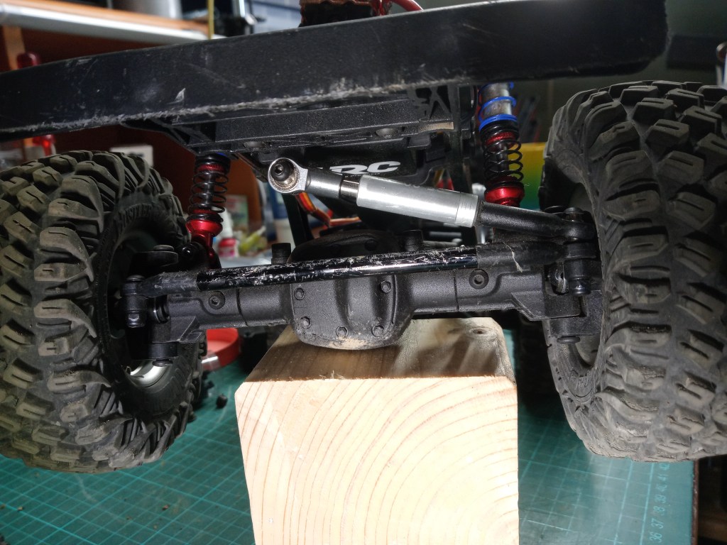
Eine weitere Modifikation zum Bausatz betrifft, die Montage der Spurstange und des Lenkhebels zum Servorarm. Dort ist die Montage unterhalb der Lenkhebel am Radträger vorgesehen. So wurde aber der Böschungswinkel vorne zu weit eingeschränkt, sodass eine höhere Montage oberhalb der Lenkhebel fällig war. Jetzt gräbt sich nur noch das voluminöse Achsgehäuse in die Erde, mit deutlich geringerem Widerstand. Schlankere und gleichzeitig, schwerere Alu-Achsen stehen schon auf der Umbauliste, was der Schwerpunktverlagerung weiter entgegenkommt.
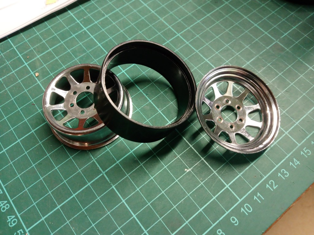
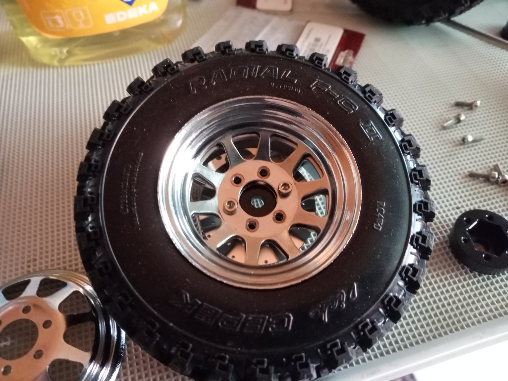
Ein besonderes Augenmerk war bei der Montage der Beadlockfelgen erforderlich, darauf will ich hier auch etwas detaillierter eingehen. Konstruktive Kritik gehört auch dazu. Der Name RC4WD steht für viele RC Produkte und doch heißt es nicht, dass auch alles zueinander passt. So würde man annehmen, das Felgen und Reifen in der Dimension 1.9 Zoll auch aufeinanderpassen. Hier der Gegenbeweis und auch ein Lösungsvorschlag. Zunächst die davon betroffene Felge in ihrem Aufbau und den Einzelteilen. Mittig der Klemmring für den Reifen, hier schwarz und aus Stahl. Links und rechts die eigentlichen Felgenteile, einmal die hier tiefgeschlüsselte Innenseite und rechts die Außenansicht. Nicht auf dem Foto, die Sechskantaufnahme zur Achse und gleichzeitig auch Aufnahme für die Gewindebolzen, um die Felgenhälften miteinander zu verschrauben. Die sieht man aber auf den nachfolgenden Fotos, in einer besonderen Ausführung.
Für die Montage wird im ersten Bauschritt im Reifenhohlraum, eine idealerweise auf das Fahrzeuggewicht angepasste Einlage aus Schaumstoff eingelegt. Danach muss der sogenannte Beadlockring in den Reifen eingeschoben werden. Er ist hier blau, darauf gehe ich aber noch im weiteren Verlauf ein.
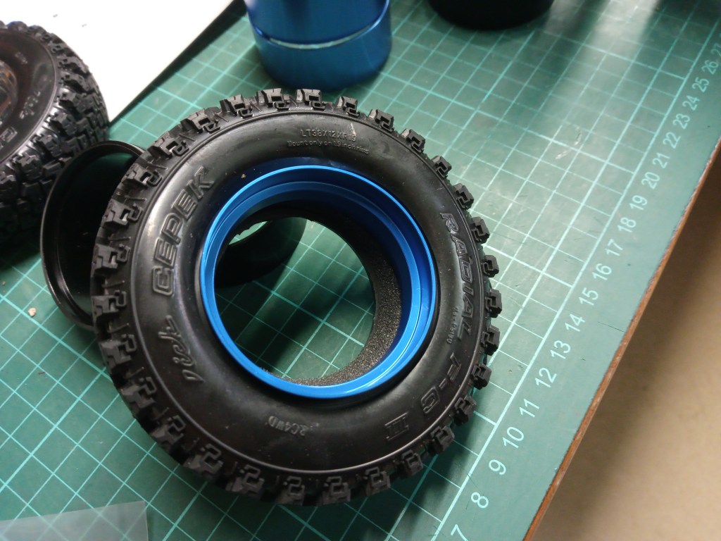
Nun ist es von großer Bedeutung, die Lage des Schaumstoffkernes und des Beadlockringes möglichst exakt auszurichten. Mit Daumen und Zeigfinger langsam, gefühlvoll und rundum, Schritt für Schritt den Schaumstoff nach innen drücken, sodass er später frei beweglich auf dem Beadlockring gleiten kann und nicht zwischen Felge und Reifen eingeklemmt werden kann.
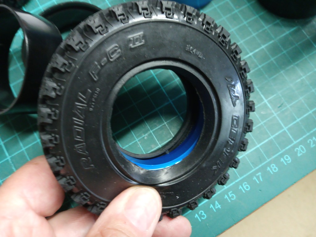
Ist dieser Schritt erfolgreich, kann das erste Felgenelement in den Reifenhohlraum eingeschoben werden. Hier ist der ungefähre Aufbau und die Lage von Felge, Reifen und Beadlockring erkennbar. Die verschiedenen Farben der Bauteile zeigt deren Lage. Im Bild 9 ist auch der Gummiwulst am Reifen erkennbar, der zwischen Felgenwulst und dem ausgedrehten Bereich des Beadlockrings eingelegt und schließlich vom Felgenrand geklemmt wird. So soll durch Reibung ein Gleiten von Reifen und Felge aufeinander vermieden werden.
Genau hier zeige ich nun das Problem bei Verwendung, des zur Felge gehörenden schwarzen Stahl-Innenringes. Zur Ansicht einmal die augenscheinlichste Erkenntnis. Die Abstufung beim schwarzen Originalring ist 3 mm tief, beim blauen ist er hingegen 5 mm tief. Um ein Problem daraus erkennen zu können, muss man die Breite der auf Bild 9 gezeigten RC4WD-Gummiwülste kennen, nämlich 5 mm.
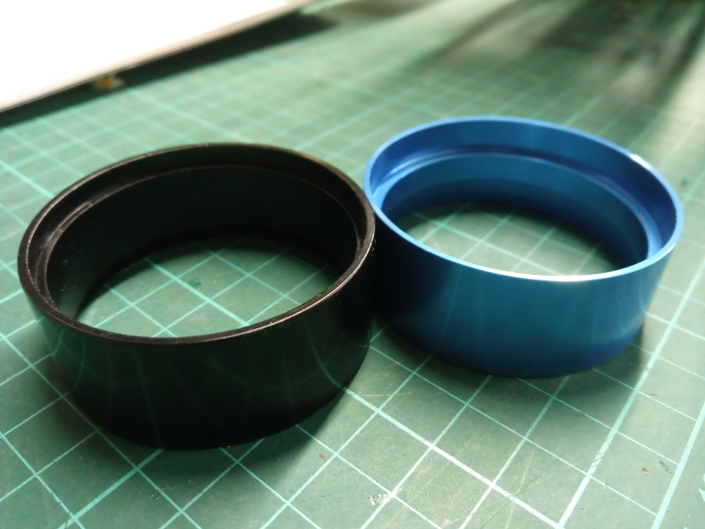
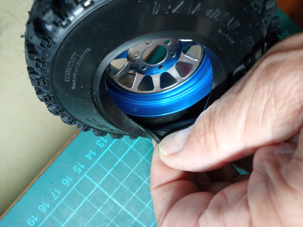
Stellt man sich nun einmal die Lage des Gummiwulstes im Beadlockring vor, sieht das fertige Montageergebnis dann so aus. Der Reifenwulst wird einseitig aus der Felge gepresst. Etwas Mathematik zur Auflockerung. 10 mm Gummi sind unterzubringen. 6 mm Platz stehen zur Verfügung. Der überschüssige Rest hier zur Ansicht! 😉
Auf der Außenseite perfekt montiert, sieht es dann wie folgt aus…
In der Praxis gibt es aber noch einen weiteren Unterschied, der über die Tiefe des ausgedrehten Randes hinausgeht. Beim blauen Alu-Beadlock-Ring ist die Ausdrehung ca. 1,7 mm im Durchmesser größer, als beim schwarzen Stahl-Ring. Das könnte in der Praxis bei schweren Fahrzeugen und extremen Winkeln zum durchrutschen oder auch ausziehen des Gummilwulstes führen. Genau das ist bei mir passiert, hat aber vermutlich andere Ursachen, die ich nachfolgend zu beschreibe versuche. Ich werde aber dennoch weitere Test machen, um die Auswirkungen fundiert zu beschreiben. Im Übrigen möchte ich auch nicht unterschlagen, dass RC4WD die blauen Ringe anbietet, um Proline-Reifen auf RC4WD-Felgen zu montieren!! Meine Interpretation und auch Schlussfolgerungen sind also mit gewisser Vorsicht zu genießen.
Daher nach diesem Exkurs weiter mit der Montage. Nachdem alle Felgenteile und der Beadlockring eingelegt worden sind, müssen die Felgenteile an den Speichen und Bohrungen zueinander ausgerichtet werden. Die 10-Speichen-Felge und 6 Radschraubenbohrungen passen nur in einer Ausrichtung übereinander, im Durchlicht erkennbar. In der oberen Felgenbohrung habe ich bereits eine Schraube zur groben Fixierung der Lage eingeschraubt.
In weiteren Schritten werden über Kreuz weitere Schrauben eingedreht. Immer schrittweise nur 1-2 Umdrehungen, sodass sich die Felgenteile möglichst parallel aufeinander zu bewegen. Wird nur einseitig angezogen, kann sich der Felgenwulst auf der gegenüberliegenden Seite herauspressen. Das braucht Geduld und ständige Kontrolle.
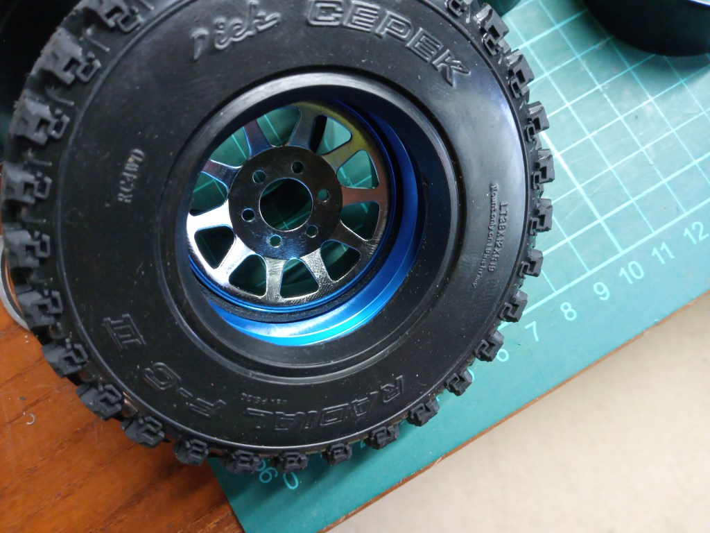
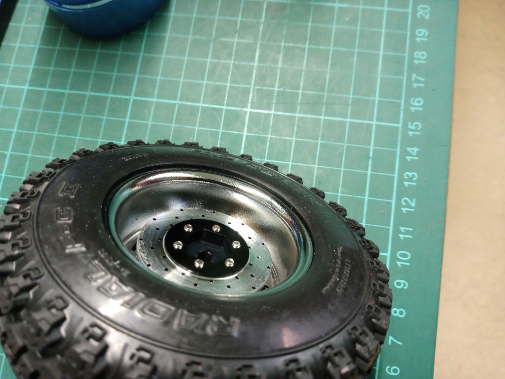
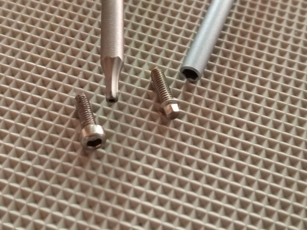
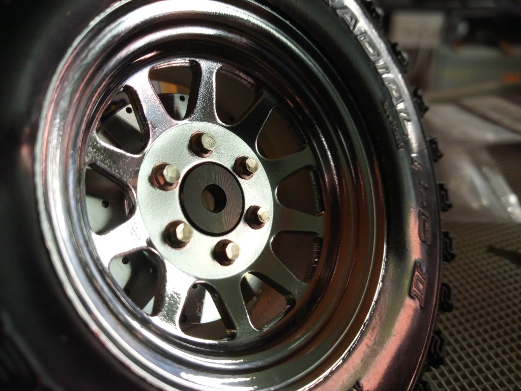
Hier nun auch die Besonderheit, die ich zum Anfang schon in Aussicht gestellt habe. Anstelle der Original-Sechskantaufnahmen, welche mit Scheibenbremsoptik. Noch etwas fürs Auge und 2 Gramm mehr Gewicht je Rad, in Achsennähe. 😄

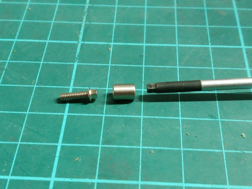
Sind schließlich alle zur Felge gehörenden Inbus-Schrauben angezogen, kommt ein weiterer Bonus der Scheibenbremsen. Der mögliche Austausch auf optisch gefällige Sechskantschrauben, ebenfalls Bestandteile des Umbausatzes.
RC4WD liefert in diesem Satz auch gleich einen unscheinbaren Adapter mit, von Inbus auf Sechskant.
Ich hatte einige Absätze vorher, vom Ausziehen des Reifenwulstes aus dem Beadlockring berichtet. Dies geschah bei einem extremen Fahrmanöver, großer Schräglage und griffigem Untergrund. Montiert war bei dieser Konfiguration der blaue Ring. Was könnten die Gründe für das Problem sein? Aber auch der zweite Reifensatz, auf den Walker Evans Legend 501 hatte dieses Problem. Hier allerdings alles in Originalkonfiguration und ebenso akkurat montiert. In beiden Fällen wurde aber zur besseren Montage, Spülmittel verwendet. Das verringerte die Reibung und sollte eigentlich einen perfekten Sitz garantieren. Den konnte ich auch tatsächlich garantieren und auch sicherstellen. Der einzige Haken, beide Reifensätze wurden unmittelbar nach der Montage in extremem Gelände bewegt. Das könnte unter Umständen ein Grund für das Schadensbild sein. Nach ein bis zwei Tagen trocknet das Spülmittel aus und die Haftreibung geht gegen Null. Vielleicht war ich einfach zu schnell. Das muss ich also noch weiter testen. Die Montage war aber ein Traum, alles glitt widerstandlos in seine Endlage.
Als vorläufige Erkenntnis werde ich zunächst einen schwarzen Stahl-Beadlockring auf 4 mm Tiefe ausdrehen lassen und dann weiter testen. Die jeweiligen Stahlringe sind 42 Gramm schwerer, als ein blauer Aluring. Also, Drehbank gesucht…😎
Die Original-Einlagen von RC4WD sind eher nicht für den Fahrbetrieb geeignet. Sie sollen wohl eher die Form der Reifen in der Verpackung stabilisieren. Schon das bisherige ca. 2,5 kg schwere Fahrgestell überforderte die Einlagen. Keine Seitenstabilität und starke Faltenbildung an den Seitenflanken bei griffigem Untergrund. Eine Kontaktaufnahme mit der Fa. RC-HP löste dieses Problem. Für die Dick Cepek F-C II bekomme ich auf das Fahrzeuggewicht abgestimmte Einlagen hergestellt. Vorlagen sind bereits vorhanden. Im Falle der Dick Cepek Trail Country, werde ich einen Reifensatz als Muster zu Verfügung stellen und bekomme auch dafür passende Einlagen, ein toller Service! Ich werde in Kürze weiter berichten.
Wird schnellstmöglich fortgesetzt…
English Version
Chassis and tire setup
Sources: RC4WD, Wikipedia, RC-HP Model building shop
It’s been a long time since I made a contribution on the subject of model making. But now I’m hooked again and I’m going to get started again. In the meantime, however, I will have to go back to my home building sites.
A few months ago, a respected Austrian modeller posted pictures of his model in the Rockcrawler forum. In the background was the still unfinished cab of a Tamiya Jeep Wrangler YJ. My enquiry about the future of this cab ended with an immediate change of ownership. From then on, there was also a short wheelbase model in my collection. Many beautiful parts, from the chrome radiator grille, cockpit, as well as the complete original kit headlights, were included in the package. In addition, metal decorations, laser-cut metal hinges, which are part of sophisticated model building. My forum colleague also knows no limits, the main thing is that the look is perfect. He has already modified some parts of the driver’s cab. Among other things, the wheel arches, the rear and the front were freed from parts. As a special feature, a fuel filler neck was installed, which was later hidden behind the number plate. That’s the history of the new model. But I won’t go into that directly today. Pictures will follow in future articles. To cut a long story short, the car still needed a chassis and that was not yet available. However, a voucher of a considerable size helped me with this luxury problem. 😏
I will not go into detail about the construction of the chassis. Hundreds of such chassis have already been documented. But overall a sovereign, accurately fitting and robustly built kit. However, it also has shortcomings. The kit axles of the CFX model version do not have ball bearings, only brass bushings are included. All links are made of plastic, but for three different wheelbases. Axle distances of 242, 252 and 267 mm can be realised with this chassis. There is no rear bumper, the front one is made of plastic. Another restriction is that the dampers are also made of plastic and finally there are the attractive but unfortunately only plastic rims in steel look. Heavy wheels, however, are an important prerequisite for a perfect driving image. For the purchase price of less than 200€, however, you get a high-quality model that gives beginners a good start. However, the passion for modelling is only just beginning and the purchase price has doubled with the first tuning stage. A ball bearing set, aluminium links and aluminium shocks, as well as a bracket for the servo mounting in the frame below the motor, which also has to be purchased, are responsible for this. But no need to mourn, quite the opposite. Team Raffee dampers, lubricated with silicone oil and special grease, and heavy aluminium wheels were mounted this way. I was and still am somewhat undecided about the rims. Two sets of wheels were available for the tuning runs. Mounted at the front, RC4WD Walker Evans Legend 501 in size 1.7 inches and at the rear the classic rim look of many off-road vehicles. In chrome and black, 1.9 inch size.
First driving tests with the kit wheels on the chrome rims, both in 1.9 inch were ended prematurely. Little to no traction, was no basis for further road tests. So back to searching and reordering. The choice of 1.7 inch tyres is very clear. Since the outer diameter had to stay well below 100 mm, the choice fell on very soft Dick Cepek Trail Country from RC4WD. I can say it in advance, a very good tyre on dry and also stony ground. Visually, they are also a feast for the eyes.
Finally, the chrome rims, for which I had chosen RC4WD Dick Cepek F-C II rubber. They are slightly larger in outside dimension but also narrower than the Trail Country. This tyre also achieved a more than satisfactory result on my current garden course. Traction-wise and also in terms of proportions, the 1.7 inch wheel set is the favourite. If it weren’t for the set goal of a Jeep with a classic noble look. A muted paint job and lots of contrasting silver and shiny chrome add-on parts are what I see before my eyes. Doesn’t that just scream for chrome rims?
So much for my initial thoughts, the history of the Wrangler and now, as usual, the technology in detail. I’ll start with the changes to the chassis itself. To repeat, all brass bushings in the axle bearings were exchanged for ball bearings. The transfer box and the main gearbox are already mounted on ball bearings in the kit. The links have been upgraded with an MST tuning kit for 242 mm wheelbase. I extended the front links by 5 mm, which increases the wheelbase to 245 mm. The front wheel is now more centred in the wheel housing.
In the kit the steering servo is to be mounted on the front axle. But I didn’t want that, even though there are not only disadvantages for this mounting place. The self-steering behaviour during compression is one such example. However, since I am constantly steering in and out when driving off-road, this is negligible, but nevertheless present. By mounting the steering servo on the axle, the distances from the steering lever to the servo horn hardly change during compression and rebound. If, on the other hand, the servo is bolted to the frame, the wheels are also deflected slightly to the left when the front left is compressed. A Panhard rod could reduce this effect, but I won’t do the work this time. I’ll just countersteer harder…. 😊
In the photo also the newly acquired 20T motor from Ruddog with 5 windings. A dream for a high torque low speed brushed motor. Completely rebuildable and all for under 30€!
Another modification to the kit concerns the mounting of the track rod and the steering lever to the servo arm. There the mounting below the steering arm at the wheel carrier is intended. But this way the angle of repose at the front was restricted too much, so that a higher mounting above the steering arm was due. Now only the voluminous axle housing digs into the ground, with much less resistance. Slimmer and, at the same time, heavier aluminium axles are already on the conversion list, which further accommodates the shift in the centre of gravity.
Special attention had to be paid to the assembly of the beadlock rims, which I will go into in more detail here. Constructive criticism is also part of it. The name RC4WD stands for many RC products and yet it does not mean that everything fits together. For example, one would assume that rims and tyres in the 1.9 inch dimension also fit together. Here is the evidence to the contrary and also a suggested solution. First of all the affected rim in its construction and the individual parts. In the middle the beadlock ring for the tyre, here black and made of steel. On the left and on the right the actual rim parts, once the inner side, here deep-set, and on the right the outer view. Not shown in the photo is the hexagonal socket for the axle and at the same time the socket for the threaded bolts to screw the rim halves together. But you can see them in the following photos, in a special design.
For the assembly, the first step is to insert a foam insert in the tyre cavity, ideally adapted to the weight of the vehicle. Then the beadlock ring has to be inserted into the tyre. It is blue here, but I will go into that later.
Now it is very important to align the position of the foam core and the beadlock ring as precisely as possible. Using your thumb and index finger, slowly, sensitively and all around, press the foam inwards step by step so that it can later slide freely on the beadlock ring and cannot get jammed between the rim and the tyre.
If this step is successful, the first rim element can be inserted into the tyre cavity. Here you can see the approximate structure and position of the rim, tyre and beadlock ring. The different colours of the components show their position. Picture 9 also shows the rubber bead on the tyre, which is inserted between the rim bead and the turned-out area of the beadlock ring and finally clamped by the rim edge. This is to prevent the tyre and rim from sliding on each other due to friction.
Exactly here I now show the problem when using the black steel inner ring belonging to the rim. Here is the most obvious finding. The gradation of the original black ring is 3 mm deep, whereas the blue ring is 5 mm deep. In order to recognise a problem from this, one must know the width of the RC4WD rubber beads shown in picture 9, namely 5 mm.
If you now imagine the position of the rubber bead in the beadlock ring, the finished assembly result looks like this. The tyre bead is pressed out of the rim on one side. Some mathematics to loosen it up. 10 mm of rubber are to be accommodated. 6 mm space is available. The surplus rest here for your perusal 😉
Perfectly assembled on the outside, it then looks like this….
In practice, however, there is another difference beyond the depth of the turned-out edge. In the case of the blue aluminium beadlock ring, the turned-out edge is approx. 1.7 mm larger in diameter than in the case of the black steel ring. In practice, with heavy vehicles and extreme angles, this could lead to the rubber bead slipping or pulling out. This is exactly what happened to me, but it probably has other causes, which I will try to describe below. However, I will carry out further tests to describe the effects in detail. By the way, I also don’t want to neglect that RC4WD offers the blue rings to mount Proline tyres on RC4WD rims!!! So my interpretation and also conclusions are to be taken with some caution.
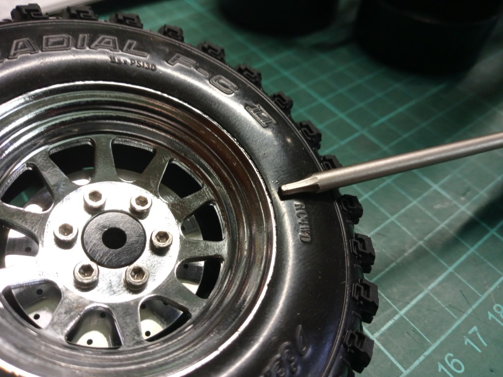
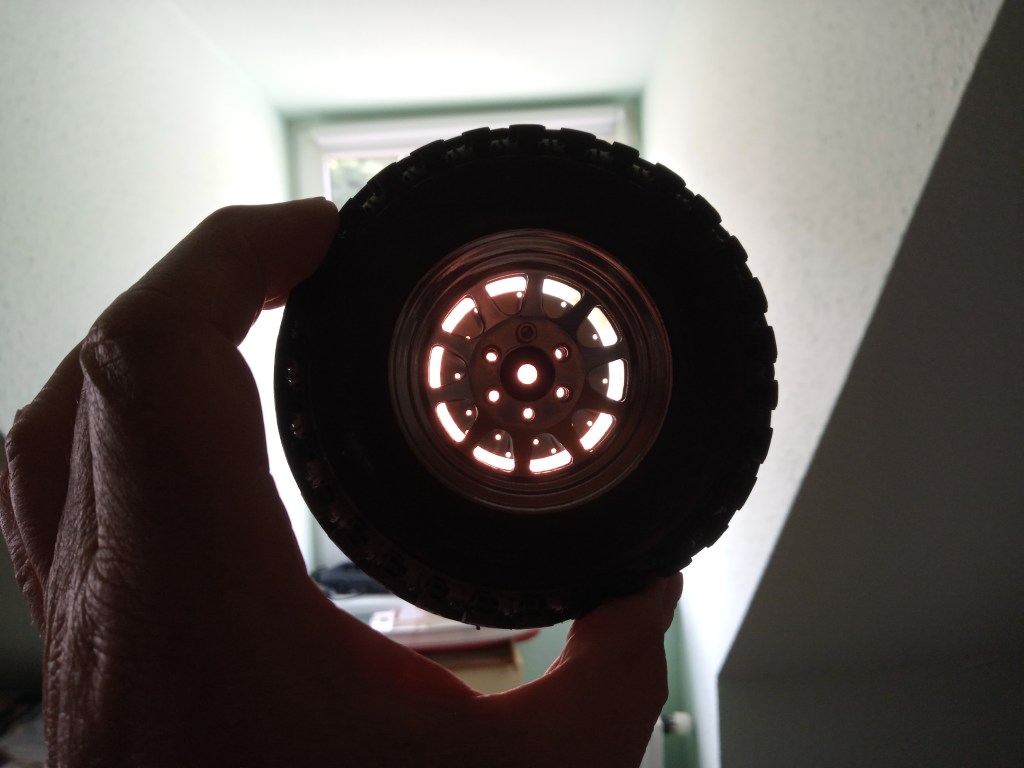
Therefore, after this digression, on with the mounting. After all rim parts and the beadlock ring have been inserted, the rim parts must be aligned with each other at the spokes and holes. The 10-spoke rim and 6 wheel bolt holes only fit on top of each other in one alignment, visible in transmitted light. I have already screwed a screw into the upper rim hole to roughly fix the position.
In further steps more screws are screwed in crosswise. Always only 1-2 turns step by step, so that the rim parts move towards each other as parallel as possible. If only one side is tightened, the rim bead on the opposite side can be pressed out. This requires patience and constant checking.
Here is the special feature I mentioned at the beginning. Instead of the original hexagonal mounts, some with disc brake optics. Something for the eye and 2 grams more weight per wheel, near the axle. 😄
Once all the Allen screws belonging to the rim have been tightened, there is another bonus of the disc brakes. They can be replaced with visually pleasing hexagonal bolts, which are also part of the conversion kit.
RC4WD also supplies an inconspicuous adapter in this set, from Allen to hexagon.
A few paragraphs earlier, I reported on the removal of the tyre bead from the beadlock ring. This happened during an extreme driving manoeuvre, on a sloping surface with good grip. Mounted was the blue ring in this configuration. What could be the reasons for the problem? But the second set of tyres, on the Walker Evans Legend 501, also had this problem. Here, however, everything was in the original configuration and mounted just as accurately. In both cases, however, washing-up liquid was used to improve the mounting. This reduced the friction and should actually guarantee a perfect fit. I was actually able to guarantee and ensure this. The only catch was that both sets of tyres were moved in extreme terrain immediately after mounting. This could possibly be a reason for the damage. After one or two days, the washing-up liquid dries out and the static friction goes to zero. Maybe I was just too fast. So I have to test this further. But the assembly was a dream, everything slid into its final position without resistance.
As a preliminary finding, I will first have a black steel beadlock ring turned out to a depth of 4 mm and then test it further. The respective steel rings are 42 grams heavier than a blue aluminium ring. So, Turning lathe wanted…😎
The original inserts from RC4WD are rather not suitable for driving. They are probably more to stabilise the shape of the tyres in the packaging. Even the previous approx. 2.5 kg chassis overtaxed the inserts. No lateral stability and strong wrinkling on the side flanks with a grippy surface. Contacting RC-HP solved this problem. For the Dick Cepek F-C II, I can get inserts made to match the weight of the vehicle. Templates are already available. In the case of the Dick Cepek Trail Country, I will provide a set of tyres as a sample and I will also get suitable inserts for them, a great service! I will report further shortly.
Will be continued as soon as possible…
Translation, with the kind support of deepl.com
