English Version
Voreilige und unüberlegte Schritte haben immer auch Konsequenzen. Geplant war ja in Reihenfolge, die Herstellung des Hilfsrahmens unter der Ladefläche. Vorab die schon beschriebenen Konsequenzen. Das Herstellen von Bohrungen und Aussparungen ist sicher nicht die aufwändigste aller Arbeiten. Es geht auch zügig vonstatten. Die so hergestellten Löcher zu schließen, eine andere Sache. Dazu habe ich die Konturen auf untergelegtes Papier übertragen, ausgeschnitten und das wiederum auf Polystyrol übertragen. Danach kommt das möglichst exakte Einpassen der beiden Teile zueinander. Im Vordergrund die Papiervorlagen, rechts ein grob vorbereitetes Bauteil und links das fertige, eingelegte Teil.

Auch die Aussparungen für die Stoßdämpferaugen waren zu verschließen. So auch hier, beidseitig kleine Maßanfertigungen.
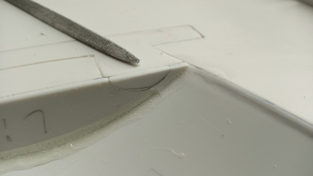
Am Übergang der inneren Radkastenabschlüsse zur Bodenplatte, gab es noch eine Schwachstelle. Zwei stumpf aufeinander geklebte Bauteile. Zur Beseitigung und gleichzeitigen Verstärkung, wurden in Folge zwei halbrunde Segmente von der bestehenden Kontur abgenommen, verklebt und eine schöne Rundung als Abschluss angebracht. Zwei Probleme mit einem weiteren Bauteil beseitigt. Die Radabdeckung besteht bis jetzt aus jeweils sechs Einzelteilen und ist noch nicht fertig. Dazu mehr im weiteren Verlauf.
Die rechte innere Abdeckung schon leicht beigearbeitet…

… und links perfekt geschliffen. Auch hier wird es noch weitere Feinarbeiten im Rahmen der Lackierung geben.
Weiter gingen die Bauarbeiten mit dem Schleifen von Ober- und Unterseite, um eine glatte Oberfläche zu schaffen. Mit einer breiten Klinge und einer Dreikant-Feile wurden Klebereste an den Übergängen beseitigt. Hier das vorläufige Ergebnis der Oberseite. Im Bild oben rechts liegt schon ein Bauteil, was später noch in anderer Form die Kotflügel zieren soll.

Und noch einmal in der hübschen Ansicht. Sie wird später leider nicht mehr sichtbar sein. Wäre es aber nicht so ausgeführt, ich würde mich bei jedem Gedanken daran ärgern. Es musste einfach möglichst realistisch aussehen.
Nach der Herstellung des Hilfsrahmens, werde ich an dieser Stelle den Überrollbügel montieren. Dazu habe ich mir auch schon einige Gedanken gemacht. Zunächst aber wieder, wie versprochen, in den Untergrund. Zum Bau der Unterkonstruktion wurde zuerst das Rahmenprofil auf Papier übertragen und in Folge auf Polystyrol-Platten.
Um auch die Optik realistisch zu gestalten, noch einige Bohrungen im Träger angebracht. Das Flachmaterial ist die spätere Basis des Winkelelementes. Mit aufgesetzten Laschen wird die Hilfskonstruktion später am Rahmen verschraubt.
Damit alles winklig wird und auch bleibt, mehrere Winkel und auch wieder meine bewährten Schwergewichte.

So sieht dann das erste Bauteil der Hilfskonstruktion an seinem Platz aus.
Nach peniblen Messungen und ebenso exakter Fixierung ist das Bauteil nun verklebt. Jetzt musste einfach alles passen, sonst waren alle Mühen umsonst. Fahrerhaus und Ladefläche sind in der Breite nahezu identisch. Jede Ungenauigkeit wäre eine Katastrophe.

Die zweite Seite ist nun ebenfalls verklebt. Davor habe ich die beiden Trägerelemente untereinander getauscht. So liegt die Basis Richtung Kotflügel, um die Hebellänge nach außen etwas zu verkürzen.
Drei Aluminium-Streben habe ich noch eingepasst. In der freien Fläche dazwischen, soll später der Fahrakku untergebracht werden. Er wird auf die zur Verfügung stehende Fläche, größenmäßig ausgelegt. Daher ist die vordere Strebe hier noch nicht endgültig. Der Zugang zum Akkufach erfolgt durch eine Klappe in der Ladefläche. Die Klappe hat ihren Drehpunkt vorne. Da auf der hinteren Ladefläche noch ein Reservereifen montiert wird, muss ich dafür auch noch eine intelligente Lösung finden. Die Arbeit geht nicht aus und das Gehirn bekommt auch noch einiges zu tun.
Eine Perspektive der späteren Anordnung, mit noch zu großem Akku.
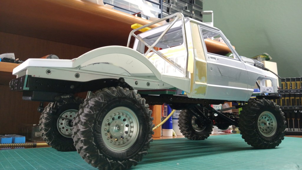
Das heutige Arbeitsergbnis in der Gesamtansicht. Der Überollbügel steht noch frei. Dessen Befestigung wird einer der nächsten Montagearbeiten sein. 😍
Wird schnellstmöglich fortgesetzt…
English Version
Small progress on the loading area
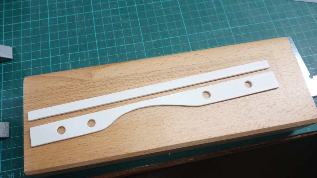
Hasty and ill-considered steps always have consequences. The plan was to make the subframe under the loading area in sequence. First of all, the consequences already described. Drilling holes and making recesses is certainly not the most time-consuming of all the work. It also goes quickly. To close the so made holes, another thing. To do this, I transferred the contours to paper, cut them out and transferred them to polystyrene. After that comes the most exact fitting of the two parts to each other. In the foreground the paper templates, on the right a roughly prepared part and on the left the finished, inserted part.
The recesses for the shock absorber eyes also had to be closed. So here too, small made-to-measure parts on both sides.
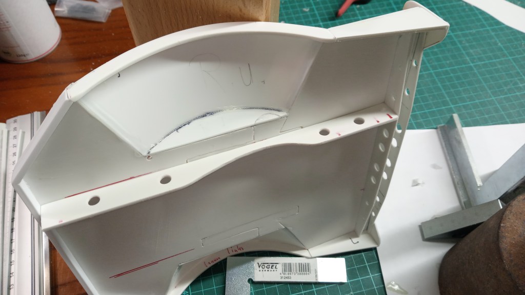
At the transition of the inner wheel arch ends to the floor panel, there was still a weak point. Two components were glued butt to butt. To eliminate and simultaneously reinforce, two semicircular segments were subsequently removed from the existing contour, glued and a nice rounding as a conclusion. Two problems with another component eliminated. The wheel cover consists so far of six individual parts each and is not yet finished. More about this later.
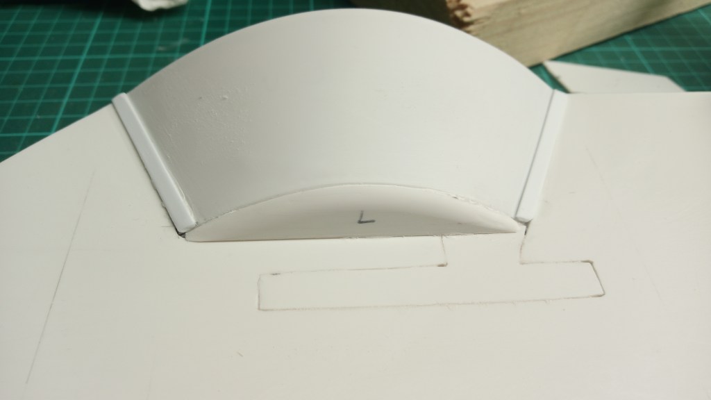
The right inner cover already slightly machined…
… and on the left perfectly sanded. Here, too, there will be more fine work in the course of painting.
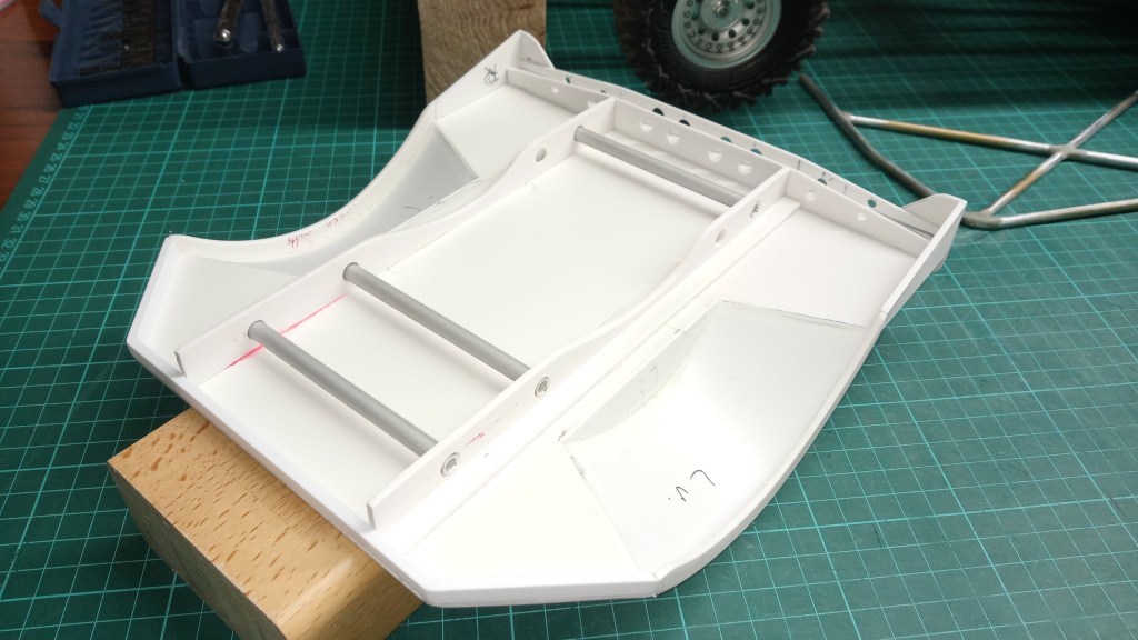
The build continued, with sanding of the top and bottom to create a smooth surface. With a wide blade and a triangular file, glue residue was removed from the transitions. Here is the preliminary result of the top side. In the picture on the top right, there is already a component that will later adorn the fenders in a different form.
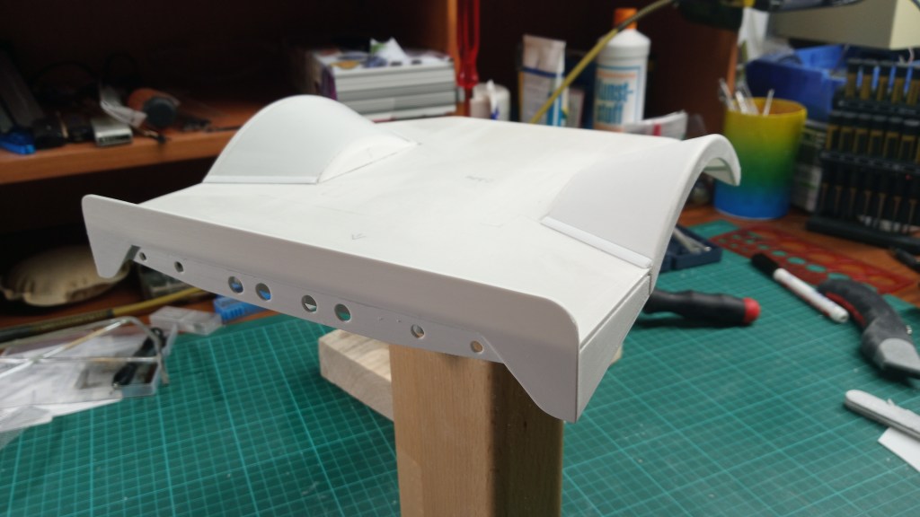
And once again in the nice view. Unfortunately it will not be visible later. But if it wasn’t done that way, I would get angry every time I think about it. It just had to look as realistic as possible.
After making the subframe, I will mount the roll bar at this point. I already had some thoughts about that, too. But first again, as promised, into the substructure. To build the subframe, first the frame profile was transferred to paper and then to polystyrene sheets.
To make also the optics realistic, still some drillings in the carrier attached. The flat material is the later base of the angle element. The auxiliary construction is later screwed to the frame with attached lugs.
So that everything becomes and also remains angular, several angles and also again my proven heavy weights.
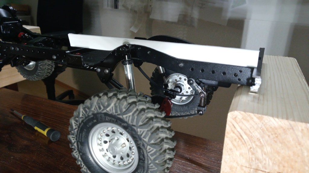
This is how the first part of the auxiliary construction looks like in its place.
After meticulous measurements and equally exact fixing, the component is now glued in place. Now everything had to fit, otherwise all efforts were in vain. The cab and the loading area are almost identical in width. Any inaccuracy would be a disaster.
The second side is now also glued. Before that, I swapped the two support elements with each other. This way the base is towards the fender to shorten the lever length a bit towards the outside.
Three aluminum struts I still fitted. In the free space between them, the battery will be placed later. It will be sized to the available area. Therefore, the front strut here is not yet final. Access to the battery compartment is through a flap in the loading area. The flap has its pivot point at the front. Since a spare tire will still be mounted on the rear cargo area, I still have to find an intelligent solution for this as well. The work doesn’t stop and the brain also gets some work to do.
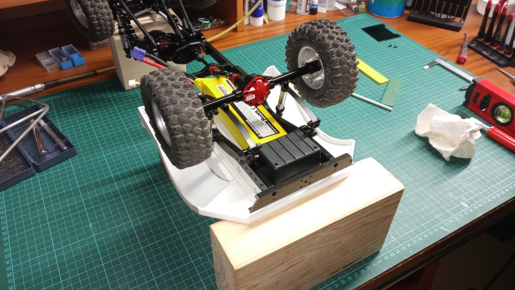
A perspective of the later arrangement, with the battery still too big.
A general view of today’s work result. The roll bar is still exposed. Its attachment will be one of the next assembly jobs. 😍
Will be continued as soon as possible…
Translation, with the kind support of deepl.com
