Quelle: snakepitrc.de
English VersionZunächst einige Worte zum aktuellen Baustand. Durch die schnelle Lieferung der vorderen Antriebswelle, ist der Antrieb ein Stück vorangekommen. Leider ist das Boom Racing Hauptgetriebe, derzeit in Deutschland noch nicht verfügbar. Das auf das schrägverzahnte Zahnrad passende Ritzel für den Motor hingegen, ist mit der Antriebswelle geliefert worden. Ein Lenkservo muss auch noch beschafft werden.
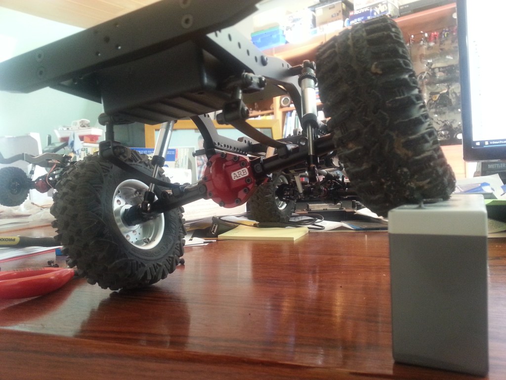
Die aktuelle Fahrwerksabstimmung hatte noch Optimierungsbedarf. Das wurde bei den ersten Trockenübungen sichtbar. Insbesondere die hintere Blattfederung musste um ihre Zukunft bangen. Glücklich war ich mit der aktuellen Konfiguration nämlich nicht. Im Vergleich zur vorderen Achsaufhängung, ist die Hinterachse, blattfedertypisch bockig. Zudem war das Fahrgestell hinten noch zu hoch. Vorne habe ich das obere Dämpferauge höher angeschraubt und damit den Abstand zum Fahrerhaus verringert. Dadurch ergibt sich eine realistischere Optik. Bei der Blattfeder habe ich dann versuchsweise die Dämpferfedern vollständig entfernt. Mit überraschendem Ergebnis. Weich und ohne Wiederstand hebt sich so das Hinterrad fast 8 cm vom Boden. Da könnten wohl noch eins, zwei Lagen Blattfedern wieder montiert werden. Wie auf dem Bild zu sehen ist, hatte ich so die Möglichkeit, die Dämpfer direkt am Rahmen zu befestigen. So montiert, decken die 90 mm langen Dämpfer den gesamten Bewegungsspielraum der Blattfeder ab. Für das untere Dämpferauge muss ich mir jetzt noch eine Halterung überlegen. Durch den schräg stehenden Dämpfer, kann das untere Dämpferauge nicht optimal angeschraubt werden.
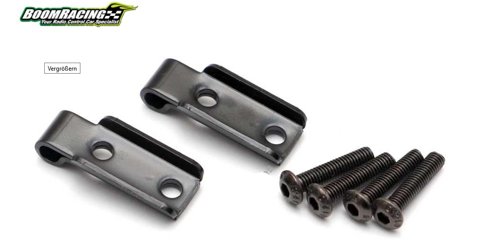
Durch eine neue Halterung, mit Anordnung des Auges hinter der Achse, wäre eine volle Ausnutzung des Dämpfer- und Blattfederweges möglich. Eine solche Halterung gibt es auch zu kaufen.

So sieht das Ersatzteil von Boom Racing dazu aus. Zwischen Achse und Blattfeder montiert, sollte sich der Stoßdämpfer, mit einer Abstandshülse montieren lassen.
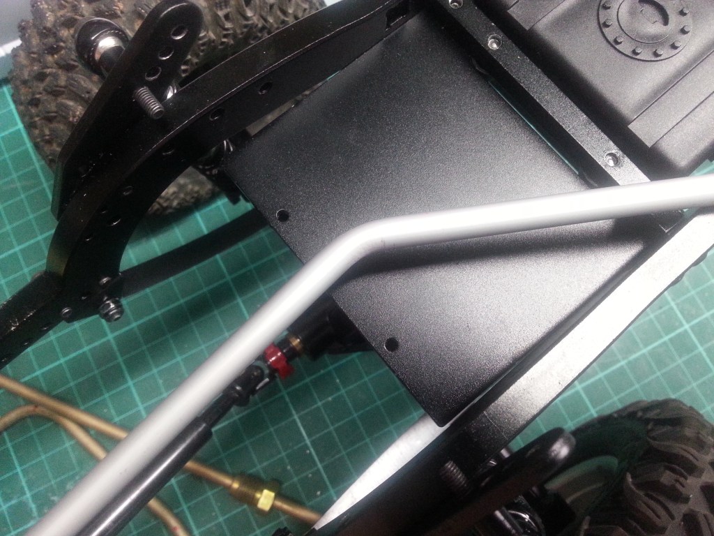
Um dem Bastelspaß auch weiterhin Raum zu lassen, habe ich erste Arbeiten für die Gestaltung hinter dem Fahrerhaus gestartet. Der Metallkäfig wird voraussichtlich eine Kombination aus PKW-Stahlbremsleitungen und Aluminiumrohren. Zum Biegen der Stahlbremsleitungen hatte ich mir schon eine Biegezange von KS-Tools gekauft. Damit lassen sich Rohre von 3, 4 und 6 mm biegen. Hier der damit gebogene Bügel, im Fahrerhaus.

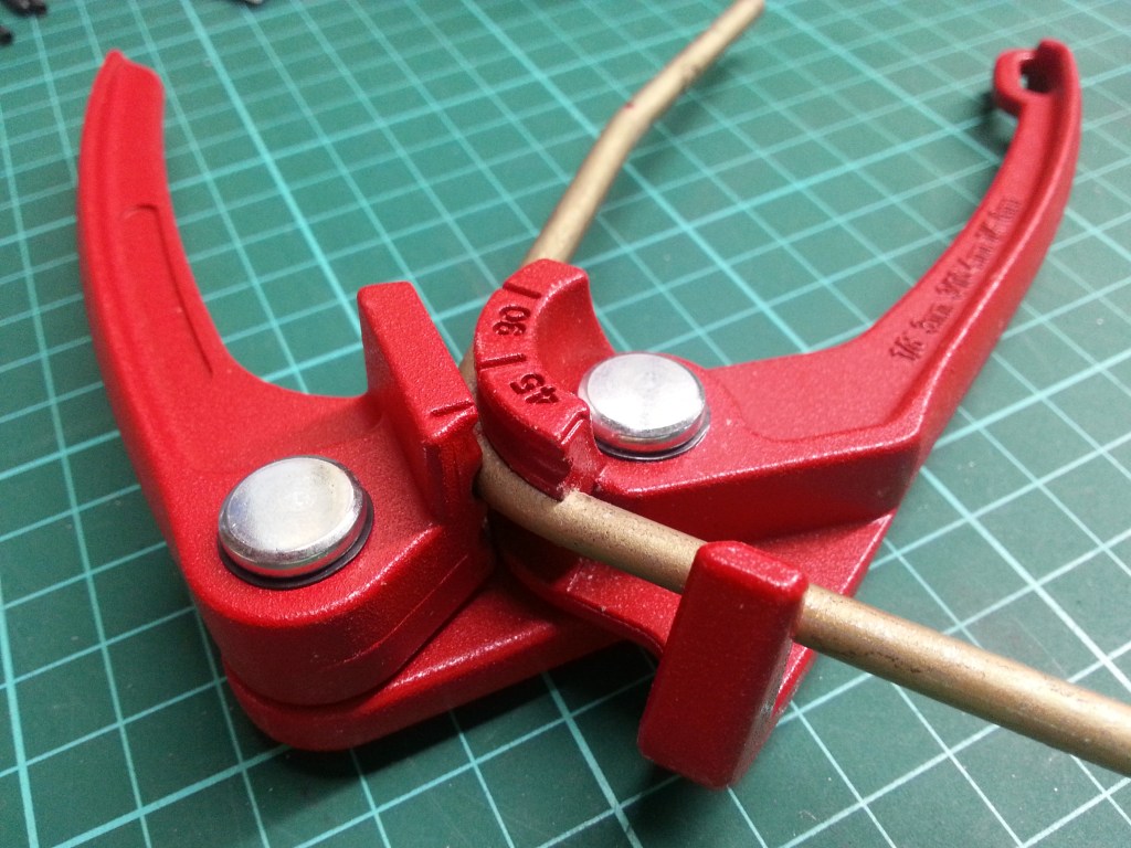
Mit dem Arbeitsergebnis bei den 4,75 mm starken Bremsleitungen war ich für den Anfang sehr zufrieden. Beim 6,0 mm Aluminiumrohr hingegen nicht ganz. Die Rohrbogen flachen etwas ab, was auch an dem härteren Material Aluminium liegen könnte. Das Ergebnis sieht dann so aus.
Im Gegensatz dazu die weichere Bremsleitung, mit nahezu unverändertem Profil.
Die Biegung im Stützrohr, wurde durch das Reserverad auf der Ladeebene nötig. Es sollte innerhalb des Bügels liegen, um bei Überschlägen geschützt zu sein. Ein gerades Rohr wäre hier, wie auch in der Realität die bessere Lösung. Ich muss also etwas umplanen. Eine alternative Montage und Abstützung werde ich im nächsten Schritt anstreben. So bleibt genügend Platz nach hinten, für das Reserverad. Das soll etwa im Winkel von mindestens 45° zum Rahmen befestigt werden.
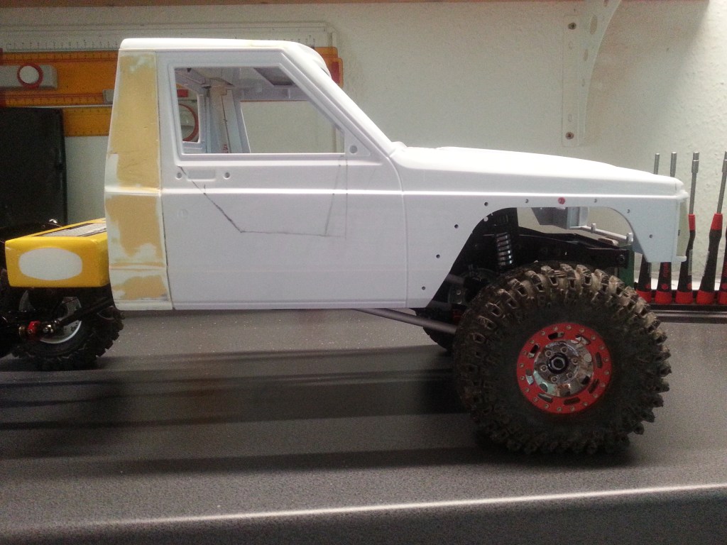
Bei einer dem Endausbau etwa entsprechenden Auflastung, sieht die Seitenansicht jetzt deutlich realistischer aus. Auf dem Foto nicht sichtbar, ist im Fahrerhaus noch ein Zusatzgewicht von 1 kg positioniert. Damit ist eine Gewichtsreserve vorhanden. Das Fahrerhaus hat jetzt schon ein Eigengewicht von 400 Gramm. Mit komplettem Innenausbau, Motor, Getriebe, Stoßstange und Seilwinde, wird sich das Gewicht auf der Vorderachse mehr als verdoppeln. Schon alleine das Getriebe hat ein Gewicht von 327 Gramm. Einschließlich Motor sind das mehr als 500 Gramm. Auf dem Bild ist auch die Markierung sichtbar, die später aus der Tür gesägt wird. An der finalen Form arbeite ich aber noch.
Im Bereich der Hinterachse ist auch schon Gewicht in Form des Akkus aufgeladen. Die zwischen den beiden Rahmenprofilen montierte Tankattrappe, wurde in diesem Schritt abgesenkt. Darin wird später der Empfänger untergebracht. Zwischen den oberen Dämpferbefestigungen, wird der Fahrtregler und die Lichtelektronik montiert. Mit der weiteren Auflastung durch Käfig, Reserverad und dem obligatorischen optischen Equipment, werde ich wohl keine ausgeglichene Gewichtsverteilung schaffen. Vielleicht bekomme ich eine 60/40 prozentige Verteilung hin. Spielraum ist aber noch vorhanden. Mit der Materialauswahl im Fahrerhaus, lässt sich noch etwas optimieren. Wobei Gewicht ja eher ein realistisches Fahrverhalten sicherstellt und das ist es ja, was mir so gefällt.

Um den Hinterbau zu gestalten, wird auf den Rahmenprofilen eine Art Plattform montiert. Diese werde ich vorab mit Bastelkarton vorbereiten. Sie wird im Endausbau vermutlich aus Aluplatten bestehen und mit Profilen am Rahmen verschraubt. Wie genau das aussieht, sehe ich wohl erst während des Baus. Eine Vorstellung habe ich schon davon. Über den Rädern wird eine Abdeckung, ähnlich der von LKWs montiert, alles in der Plattform integriert. Die sichtbare Oberseite erhält einen Belag, aus einer profilierten Alubeplankung.
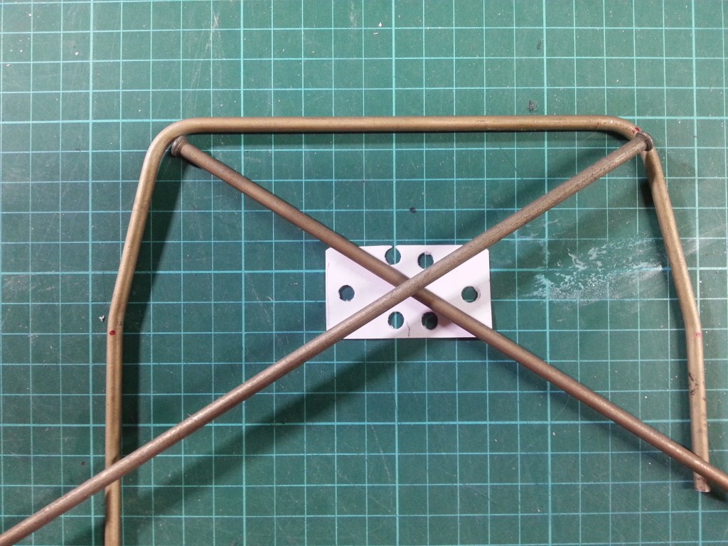
Dekorativ stelle ich mir vor dem Reserverad noch einen Zusatzkühler mit funktionsfähigem Mikrolüfter vor. Den Entwurf des Überrollbügels habe ich auch schon angefangen. Er steht auf einem eigenen Rahmenausleger, der unmittelbar am Fahrerhaus, direkt mit dem Rahmen verschraubt wird. Das Papier stellt das Knotenblech dar, auf dem ich mit einem Locher die Bohrungen darstellen wollte. Beim Bohren in Alublech werde ich das sicher exakter hinbekommen und auch filigraner. 😉
Wird schnellstmöglich fortgesetzt…
English Version
The Comanche Truggy in the development phase
Source: snakepitrc.de
First a few words about the current state of construction. Due to the fast delivery of the front drive shaft, the drive has made some progress. Unfortunately, the Boom Racing main gearbox is not yet available in Germany. The pinion for the engine, however, which fits on the helical gear, has been delivered with the drive shaft. A steering servo still has to be procured.
The current chassis tuning still had to be optimized. This became visible during the first dry runs. Especially the rear leaf suspension had to fear for its future. I was not happy with the current configuration. Compared to the front axle suspension, the rear axle is typically stubborn. In addition the rear chassis was still too high. In the front I screwed the upper damper eye higher and thus reduced the distance to the cab. This results in a more realistic look. For the leaf spring I removed the damper springs completely. With surprising results. Softly and without resistance the rear wheel lifts up almost 8 cm from the ground. You could probably mount another one or two layers of leaf springs. As you can see on the picture, I had the possibility to mount the shocks directly on the frame. Mounted this way, the 90 mm long shocks cover the whole range of movement of the leaf spring. For the lower shock eye I have to think about a mounting bracket. Because of the slanted position of the shock, the lower shock eye cannot be screwed on optimally.
A new mount, with the eye located behind the axle, would allow full use of the damper and leaf spring travel. Such a bracket is also available for purchase.
This is what the spare part from Boom Racing looks like. Mounted between axle and leaf spring, it should be possible to mount the shock absorber with a spacer sleeve.
In order to leave room for the crafting fun, I started first works for the design behind the cab. The metal cage will probably be a combination of passenger car steel brake lines and aluminum pipes. For bending the steel brake lines I had already bought a bending pliers from KS-Tools. With these pliers tubes of 3, 4 and 6 mm can be bent. Here the bended bracket, in the driver’s cab.
I was very satisfied with the results of the work on the 4.75 mm thick brake lines for the beginning. With the 6.0 mm aluminum tube however not quite. The pipe bends are flattened a little bit, which could be due to the harder material aluminum. The result looks like this.
In contrast, the softer brake line, with almost unchanged profile.
The bend in the support tube, became necessary because of the spare wheel on the loading level. It should be inside the stirrup to be protected in case of rollovers. A straight tube would be the better solution here, as in reality. So I have to replan something. An alternative mounting and support I will strive for in the next step. So there is enough space to the back for the spare wheel. This should be mounted at an angle of at least 45° to the frame.
With a load that is about the same as the final assembly, the side view looks much more realistic now. Not visible on the photo, an additional weight of 1 kg is positioned in the cab. This provides a weight reserve. The driver’s cab already has a tare weight of 400 grams. With complete interior fittings, engine, transmission, bumper and winch, the weight on the front axle will more than double. The transmission alone weighs 327 grams. Including the engine, that is more than 500 grams. On the picture you can also see the markings that will later be cut out of the door. But I am still working on the final shape.
In the area of the rear axle weight is already charged in the form of the battery. The dummy tank mounted between the two frame profiles was lowered in this step. The receiver will be placed in it later. Between the upper damper mountings, the speed controller and the light electronics are mounted. With the further load by cage, spare wheel and the obligatory optical equipment, I will probably not create a balanced weight distribution. Maybe I will get a 60/40 percent distribution. But there is still room for improvement. With the material selection in the driver’s cab, something can still be optimized. The weight ensures a more realistic driving behavior and that’s what I like.
To design the rear end, a kind of platform is mounted on the frame profiles. I will prepare this platform in advance with handicraft cardboard. In the final stage it will probably consist of aluminium plates and will be screwed to the frame with profiles. How exactly this will look like, I will probably only see during the construction. I already have an idea of it. Above the wheels a cover, similar to that of trucks, will be mounted, everything integrated into the platform. The visible upper side gets a covering, made of a profiled aluminium planking.
Decoratively, I imagine an additional radiator with a functional micro-fan in front of the spare wheel. I have already started the design of the roll bar. It stands on its own frame arm, which is bolted directly to the cab, directly to the frame. The paper represents the gusset plate, on which I wanted to show the drillings with a hole punch. When drilling in aluminum sheet metal, I will certainly be able to do this more precisely and also more filigree. 😉
Will be continued as soon as possible…
Translation, with the kind support of deepl.com
