Quellen:
English Version
Auf der oberen Plattform habe ich eine Schellenkonstruktion montiert, um die Druckleitung senkrecht an ihrem Platz zu halten. Alles wieder aus Zinkblech-Resten gebaut.
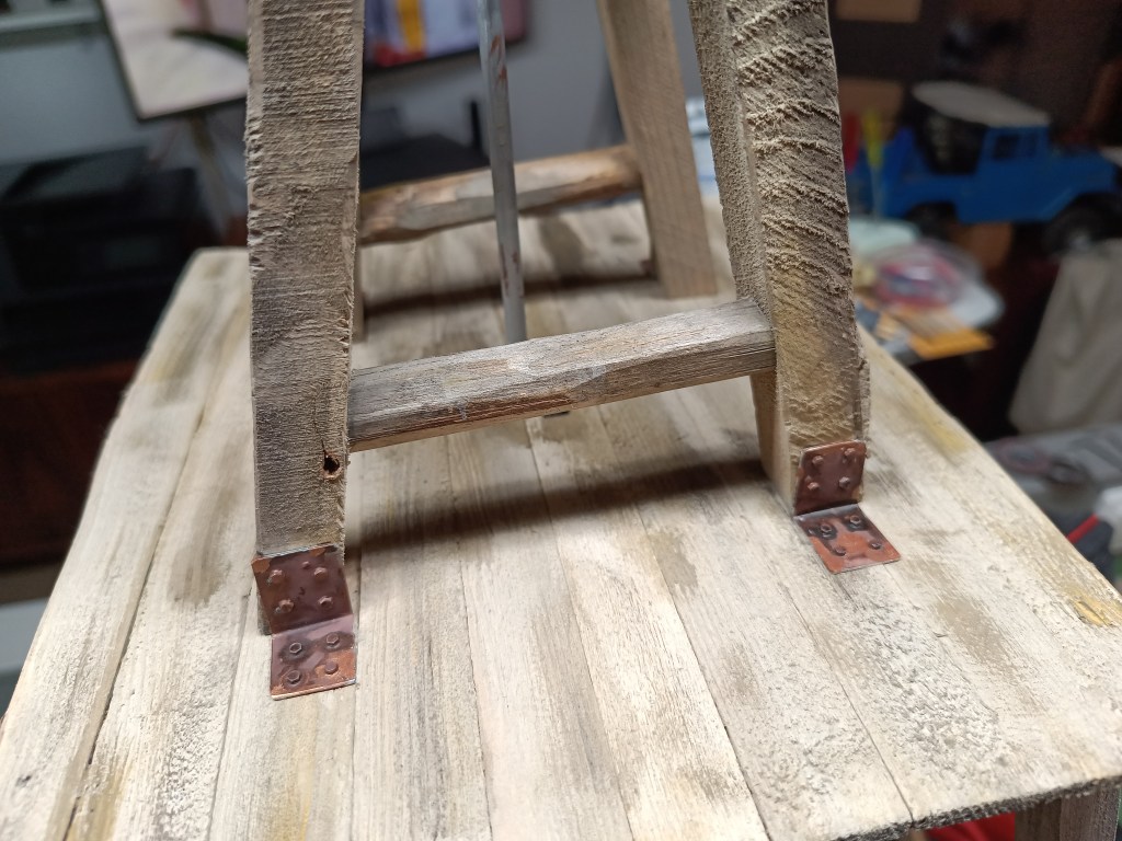
Der vierbeinige Unterbau des Windrotors, wurde mit Winkelblechen aus Titanzink am Turm verschraubt.
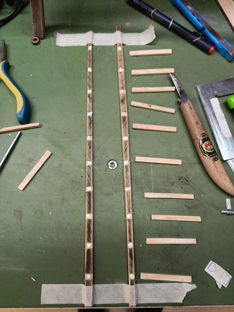
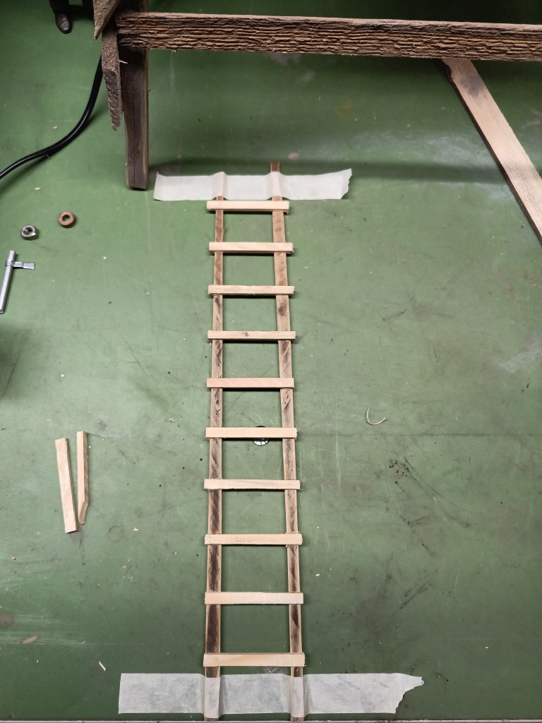
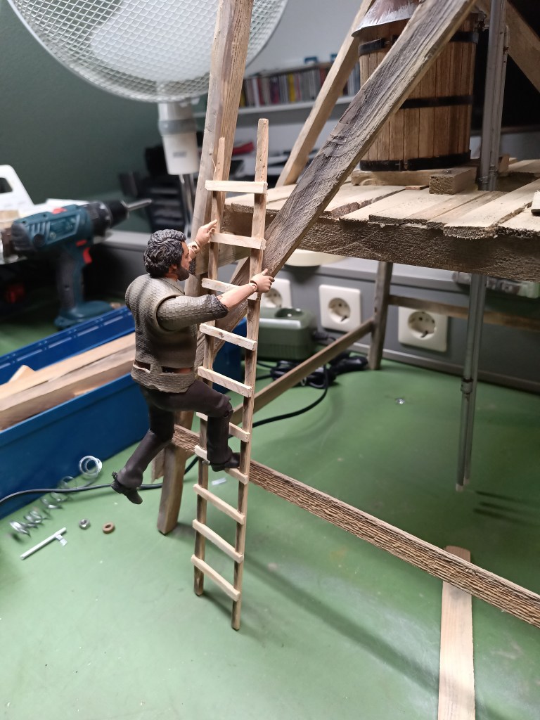
Um die untere Plattformebene zu erreichen, habe ich eine Leiter gebaut.
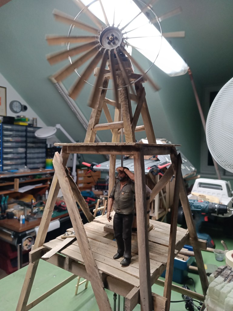
In diesem Bereich gibt es neben dem Wassertank auch noch einen Ausblick.
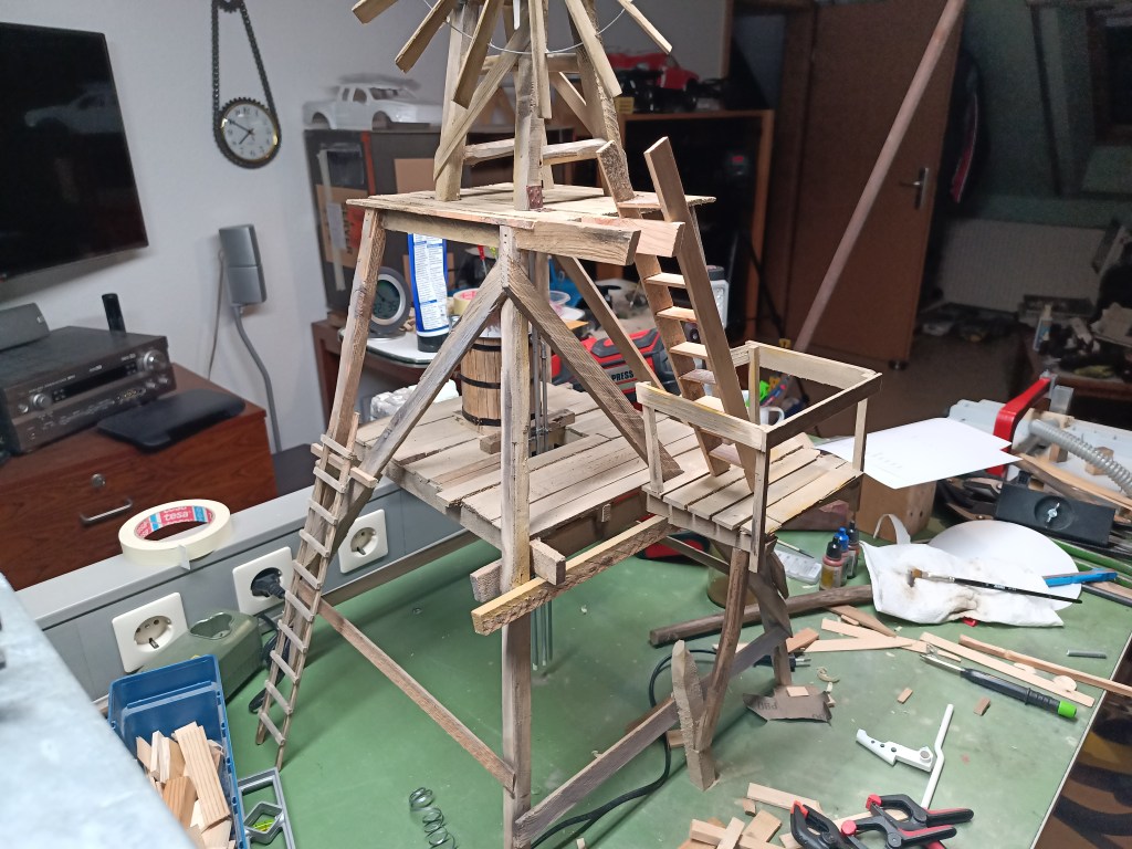
Dann dachte ich auch noch an einen weiteren Aufgang zur Rotor-Plattform. Einige Traversen als Unterbau, einen Boden aus Brettern und ein Geländer wurden dazu angebaut.
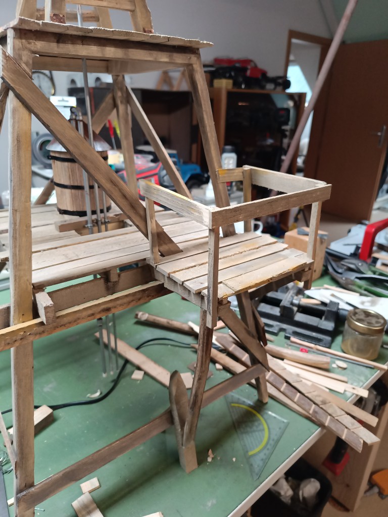
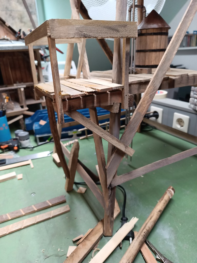
Anstelle einer Leiter, habe ich mich an dieser Stelle kurzfristig zum Bau einer Treppe entschieden. Gefräste Taschen und ein paar Trittstufen….
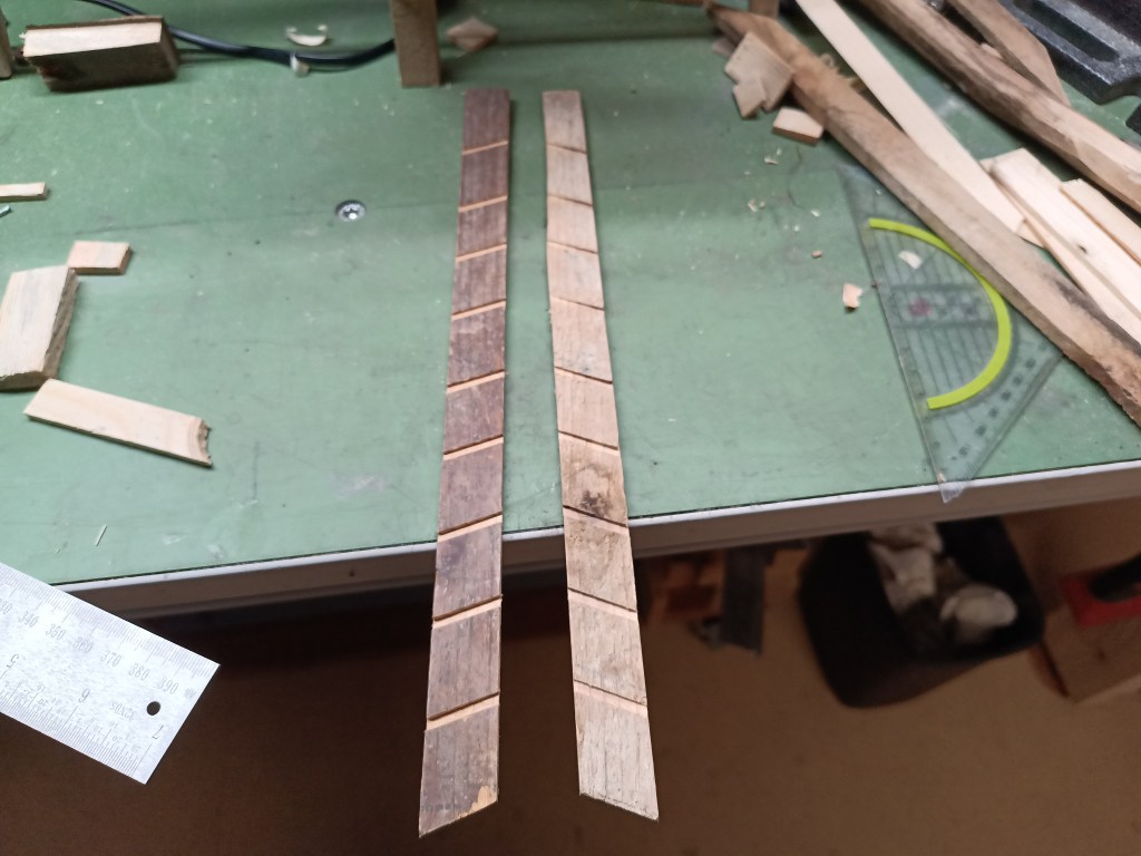
… für die neue alte Treppe.
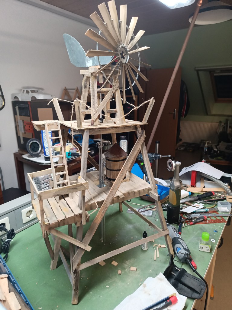
Auch hier hatte ich noch eine Trittfläche für den Austritt montiert. Letztendlich noch einige Pfosten, um gesichert rund um das Windrad laufen zu können. Das als Sicherung vorgesehene, rustikale Naturseil hängt leider nicht schön durch und wird sicher noch gegen etwas realistischeres ausgetauscht.
Bevor es mit der Bodenplatte in die letzte Runde geht, habe ich mir noch eine Entleerung für den Wassertank ausgedacht. Mit zwei Kunststoffresten fing es an.
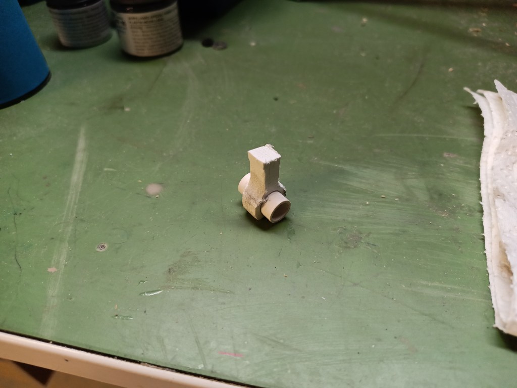
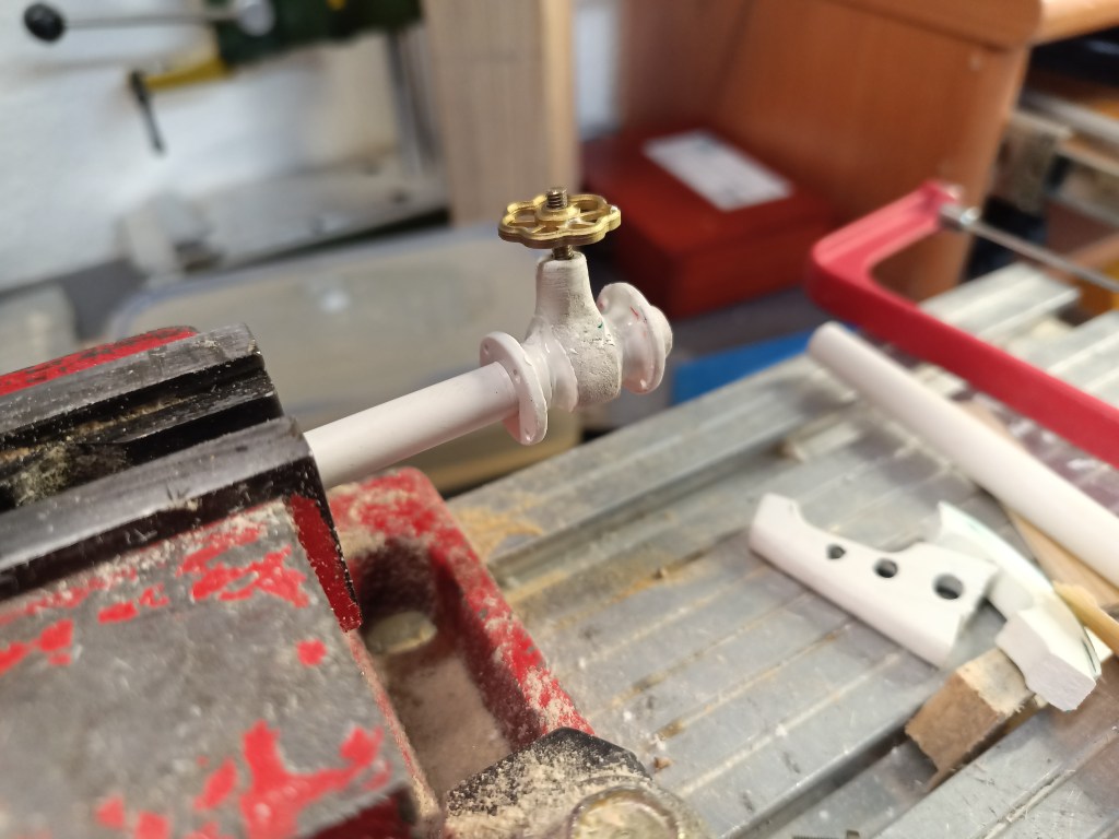
Das Gehäuse wurde mit einem Schleifstift am Dremel in Form gebracht. Eine Schraube M3 diente als Spindel. Ein zugekauftes Messing-Handrad verbesserte die Optik so richtig. Aus Resten von 2,5 mm Kunststoffplatten entstanden die Flansche. Die Maße und Bohrungen wie bei einem Originalteil. Der Schieber hat somit die Dimension DN65. Mit Vallejo Plastic Putty wurden die Übergänge abgerundet.
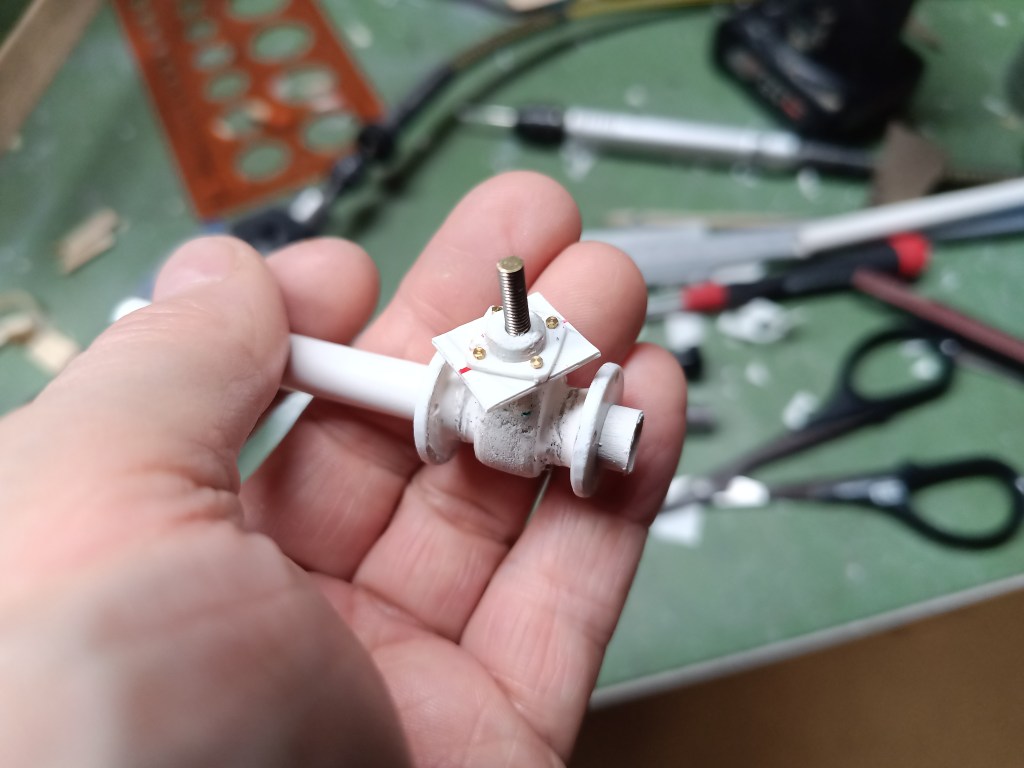
Der obere Abschluss der Stopfbuchse entstand aus zwei miteinander verschraubten Kunststoffresten, die maßhaltig angeglichen wurden.
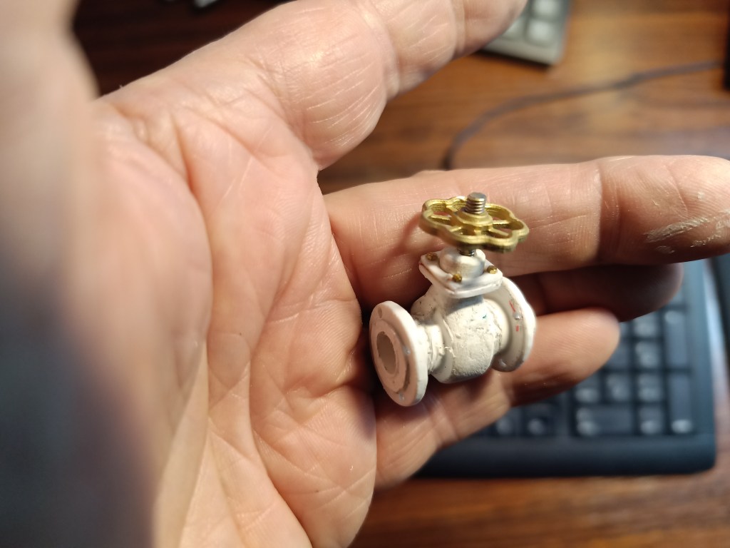
Es sieht so auch schon richtig echt aus. Der abgedrehte Bund der Dichtfläche wurde durch ein aufgeklebtes, gebohrtes und rundgeschliffenes Kunststoffplättchen dargestellt. Jetzt nur noch die Konturen schleifen…😏
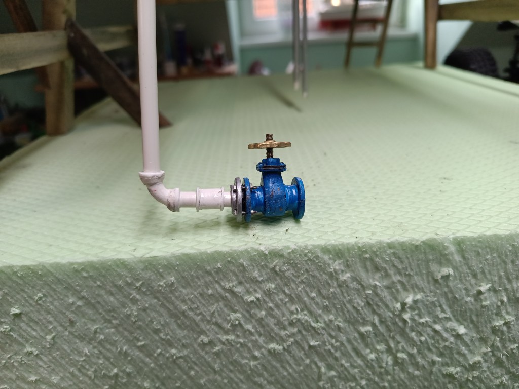
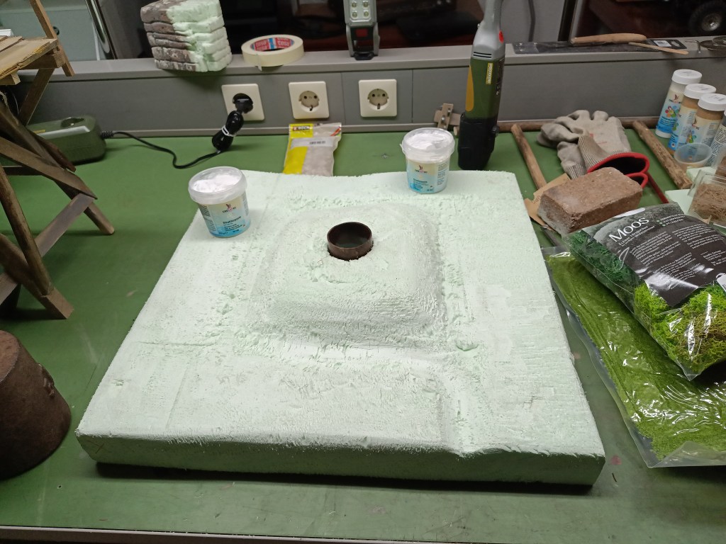
Mit der Rohrleitung verbunden, sieht das Ergebnis wie folgt aus. Die ausgeschnittene Grundplatte aus Styrodur ist im Hintergrund auch schon erkennbar.
Sie wurde in der Höhe noch einmal halbiert und so geformt, dass ein Hügel im Zentrum zurückgeblieben ist. Darin befindet sich das Brunnenrohr, dass bereits verrostet aus dem Boden ragt.
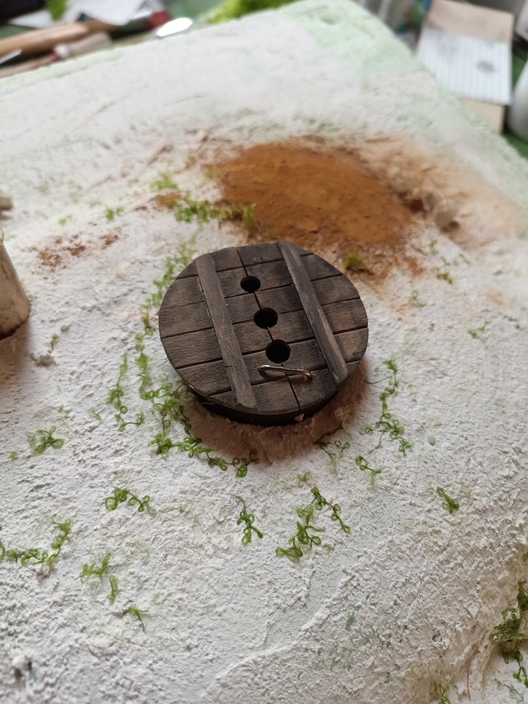
Eine Brunnenschachtabdeckung hatte ich auch dafür gebaut, wieder aus Eisstäbchen.
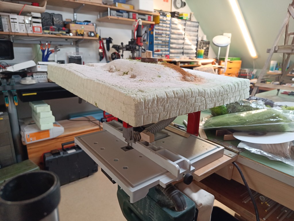
Die Oberfläche wurde mit Strukturpaste gespachtelt und der Sockel mit einer Bruchsteinmauer-Struktur versehen.
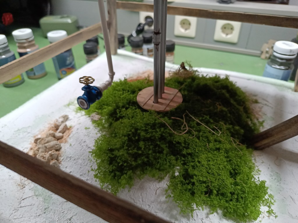
Ein erster Blick in die Zukunft, zeigt Teile der späteren Optik.
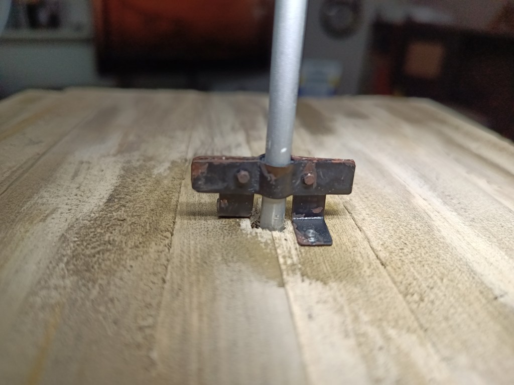
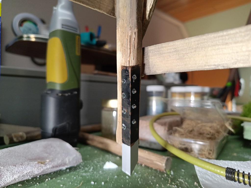
So weit bin ich aber bisher nur in Gedanken. Weiter ging es mit vier im Boden versenkten Metallwinkeln. Acht Schrauben je Maststütze sorgen für einen sicheren Stand. Auch die Hammerschläge sind an den Bodenankern erkennbar. Rost gibt es auch schon.
Aus Mangel an Arbeitsmaterial wird die farbliche Gestaltung auf den nächsten Beitrag verschoben, der dann etwas kürzer ausfällt.
Wird schnellstmöglich fortgesetzt…
English Version
Wind-powered water pumping Part
Sources: Internet image search
On the upper platform, I installed a clamp construction to hold the pressure pipe vertically in place. Everything was built from leftover zinc sheet metal.
The four-legged base of the wind rotor was bolted to the tower with titanium zinc angle brackets.
I built a ladder to reach the lower platform level.
In addition to the water tank, this area also offers a view.
Then I thought of adding another staircase to the rotor platform. A few crossbars were added as a substructure, along with a floor made of boards and a railing.
Instead of a ladder, I decided at short notice to build a staircase at this point. Milled pockets and a few steps…
…for the new old staircase.
Here, too, I had installed a step for the exit. Finally, a few posts were added so that it is safe to walk around the wind turbine. Unfortunately, the rustic natural rope intended as a safety measure does not hang nicely and will certainly be replaced with something more realistic.
Before moving on to the final stage with the base plate, I came up with a drainage system for the water tank. It started with two pieces of plastic scrap.
The housing was shaped using a grinding pin on a Dremel. An M3 screw served as the spindle. A purchased brass handwheel really improved the appearance. The flanges were made from scraps of 2.5 mm plastic sheets. The dimensions and drill holes are the same as on an original part. The slide valve thus has the dimension DN65. The transitions were rounded off with Vallejo Plastic Putty.
The upper end of the stuffing box was made from two pieces of plastic scraps screwed together and adjusted to the correct dimensions.
It already looks really real. The turned collar of the sealing surface was represented by a glued-on, drilled, and rounded plastic plate. Now all that’s left is to sand the contours…😏
Connected to the pipeline, the result looks like this. The cut-out base plate made of Styrodur is also already visible in the background.
It was halved in height and shaped so that a hill remained in the center. Inside is the well pipe, which is already rusted and protruding from the ground.
I also built a well shaft cover for it, again from popsicle sticks.
The surface was smoothed with textured paste and the base was given a quarry stone wall texture.
A first glimpse into the future shows parts of the later appearance.
But so far, I’m only there in my mind. I continued with four metal brackets sunk into the ground. Eight screws per mast support ensure a secure footing. The hammer marks are also visible on the ground anchors. There is already some rust.
Due to a lack of working materials, the color design will be postponed until the next post, which will then be a little shorter.
Will be continued as soon as possible…
Translation, with the kind support of deepl.com
