Quellen:
English Version
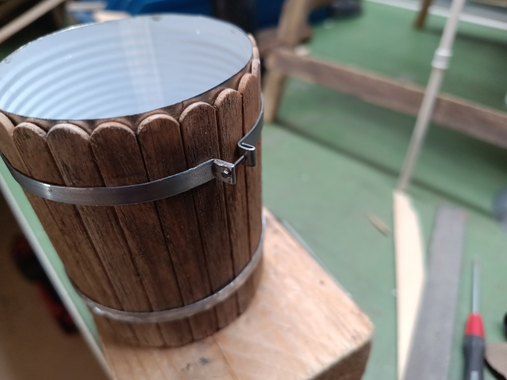
Weiter ging es mit der Baustelle Wasserförderung. Zuerst wurden auch am Wassertank drei Verstärkungsbänder montiert. Sie sind sogar mit Schrauben und Muttern versehen, um die Holzplanken vorzuspannen.
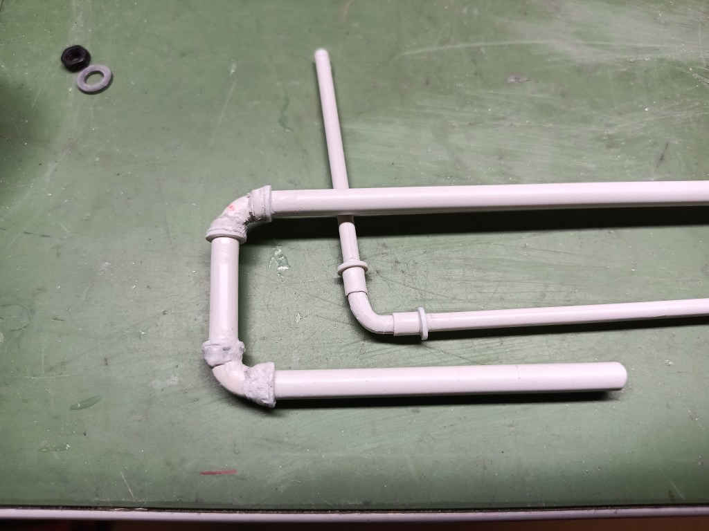
Die Fittings an den Rohren sind nur der Optik halber entstanden. Dazu wurden zwei verschiedene Wege gewählt. Begonnen hatte es bei beiden Varianten mit dem Biegen des Rohres um 90 Grad. In einem Fall wurde ein Rohr auf das fertig gebogenen Kunststoffstab aufgeschoben und verklebt. Es stellt die Aufweitung dar, in den das Rohr geschraubt wird. Gussfittings haben i.d.R. zusätzlich einen Verstärkungswulst am Gewindeanfang. Rohrgewinde sind nach hinten konisch zulaufend und beim vollständigen Einschrauben fast metallisch dicht. Der Verstärkungswulst nimmt diese Kräfte mit auf. Dieser Wulst wurde aus gebohrten Kunststoffresten 1 mm hergestellt und aufgeklebt.
Am dickeren Rohr wurde die Aufweitung für das Gewinde zweilagig gespachtelt. Nachfolgend noch einmal die unbearbeiteten Teile.
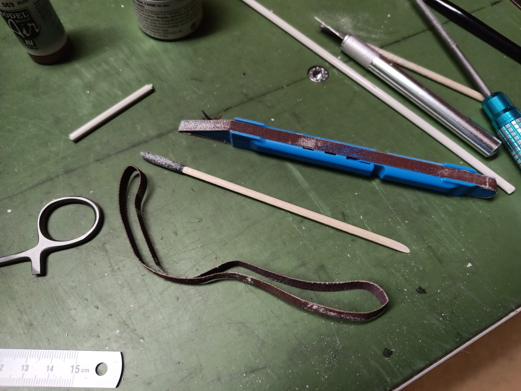
Mit speziellen Flach- und Rundfeilen bin ich dem Spachtel an die Substanz gegangen.
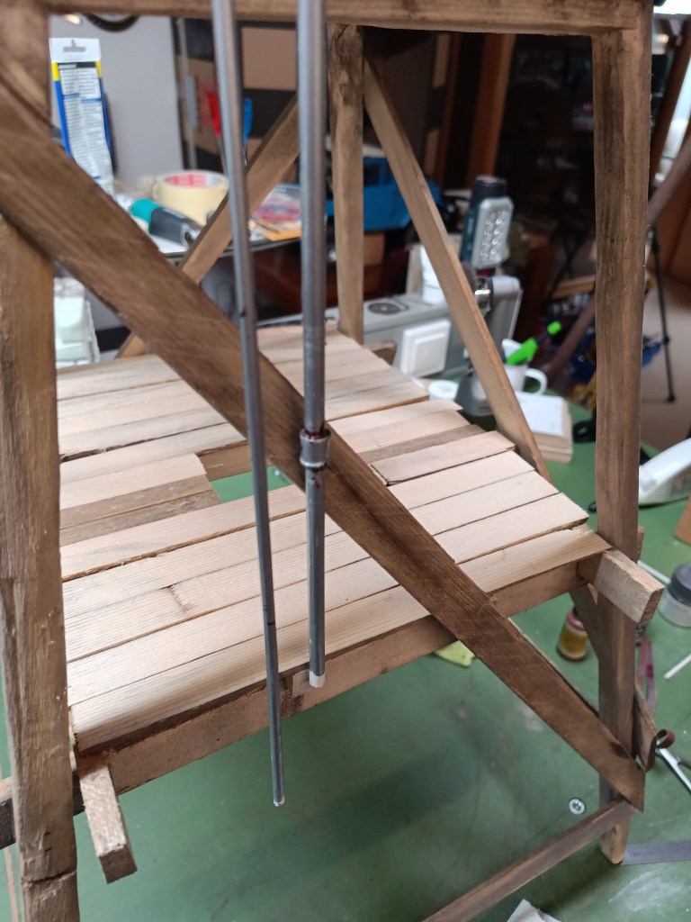
Nach dem Lackieren sind auch die ersten Roststellen an den geschnittenen Rohrgewinden sichtbar. Die Füllleitung von oben und eine Überlaufleitung.
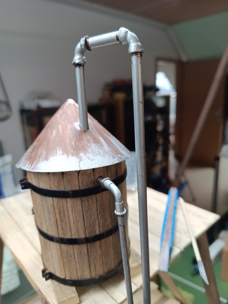
In die Füllleitung hatte ich auch noch eine Verbindungsmuffe eingebaut. Auf dem Foto ist auch schon das erste Ergebnis der Holzalterung zu sehen.
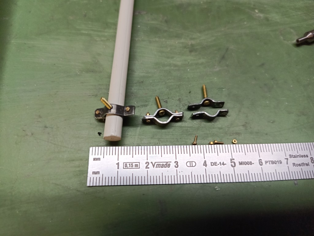
Damit die Rohre nicht frei im Raum hängen, habe ich mir eine sachgerechte Befestigung gebaut. Schmale Blechstreifen wurden links und rechts mit der Flachzange um das Rohr geformt. Das ergab die typische Schellenform um Rohre zu befestigen. Eine Holzschraube hält den Halter auf dem Untergrund, Messingmuttern M0,8 und passende Schrauben die Schellenhälften zusammen.
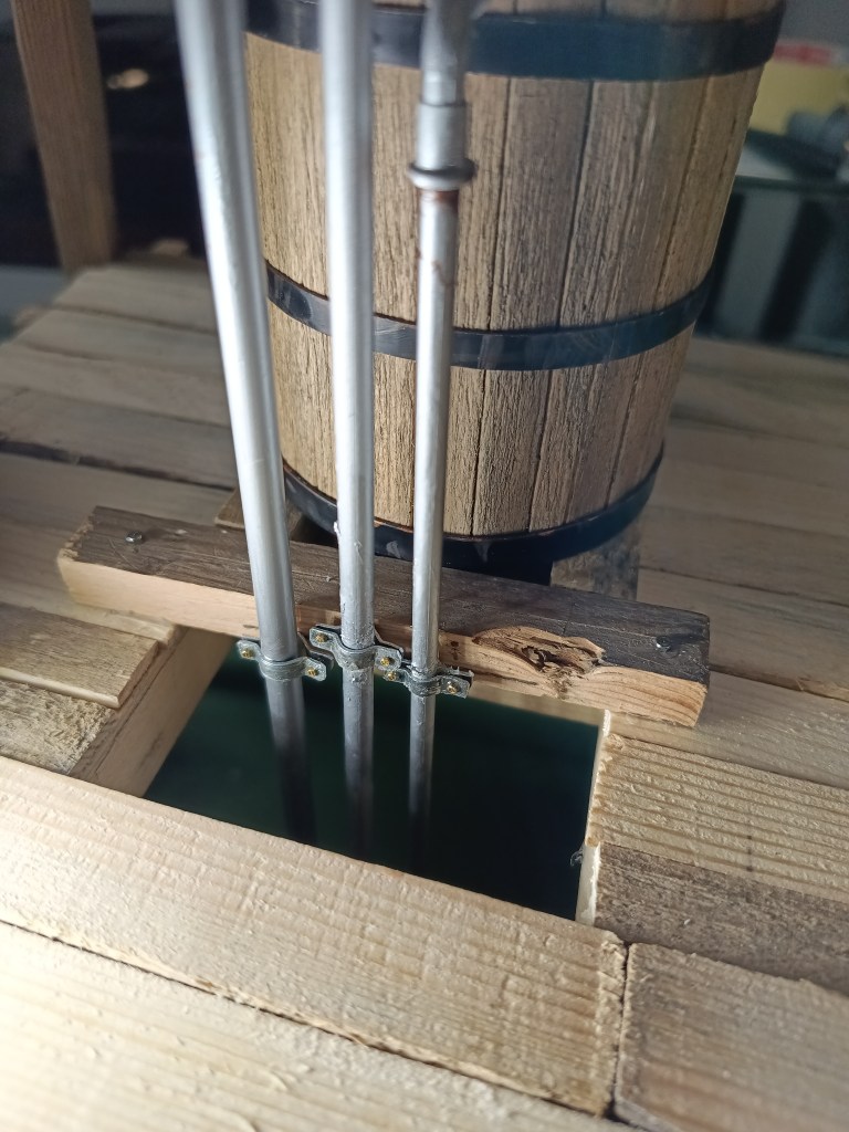
Ein Querbalken wurde vor dem Wassertank auf dem Boden verschraubt und dient als Halterung für die drei Schellen.
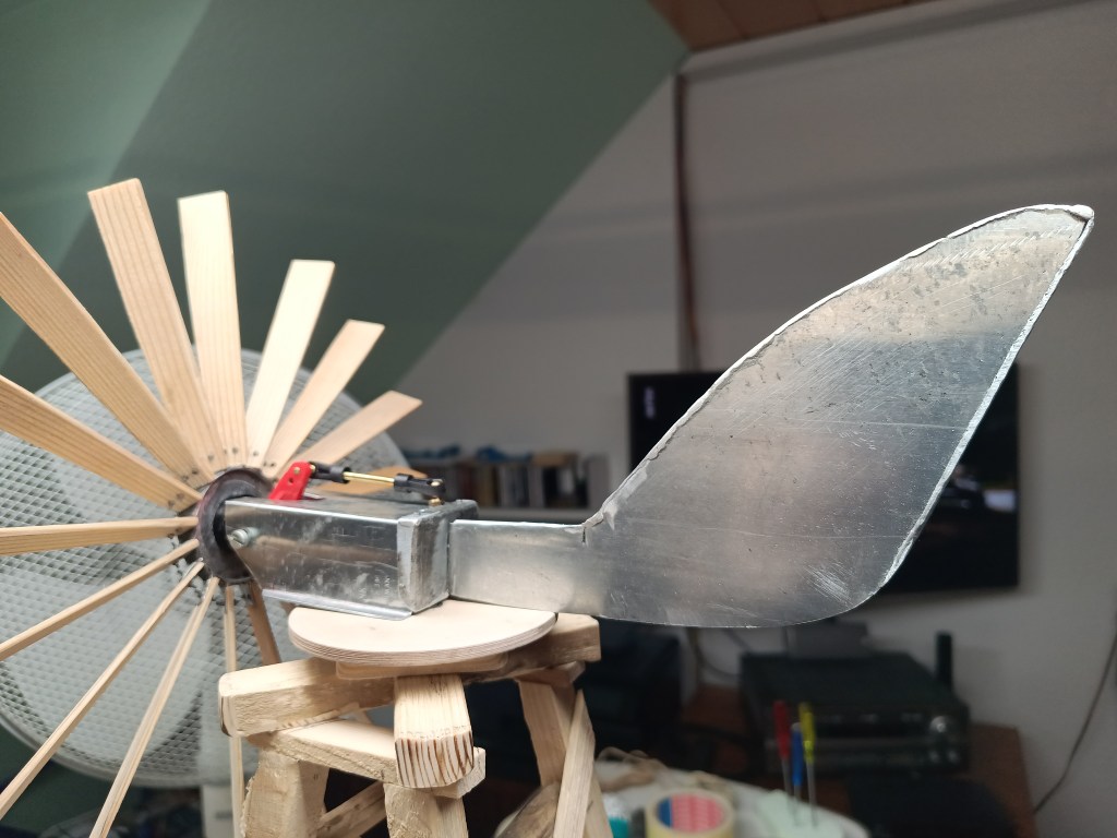
Die Windfahne wurde auch noch etwas abgespeckt und soweit erleichtert, um am Drehpunkt eine Balance zum Rotor zu bekommen.
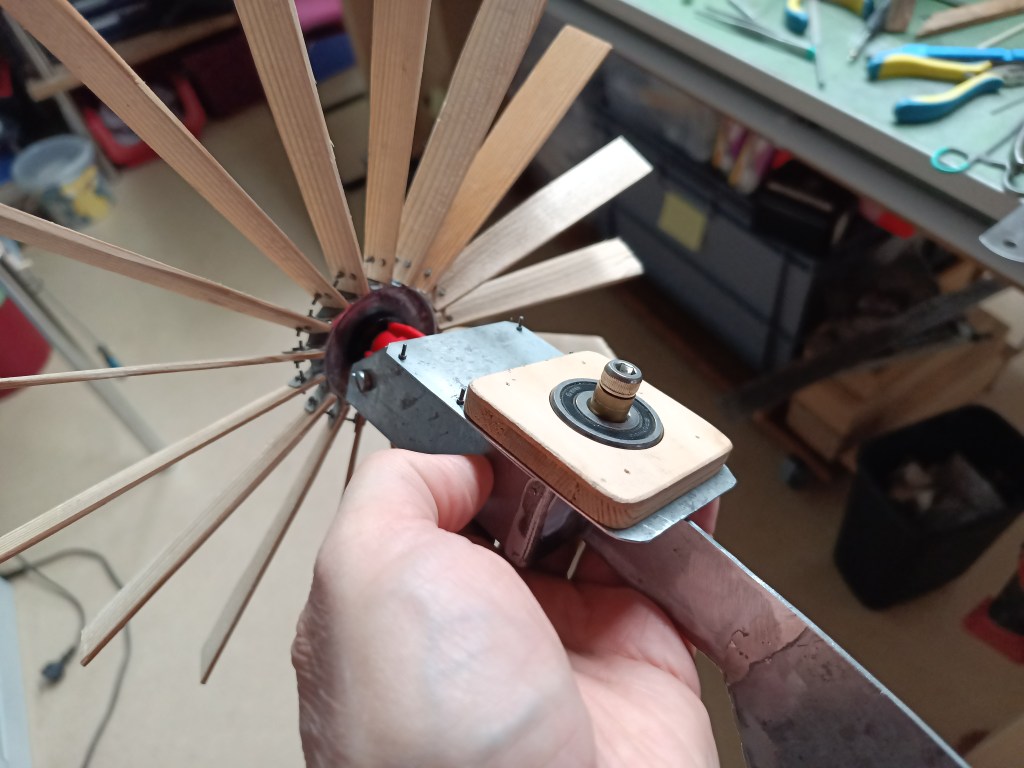
Der Unterbau des Drehlagers wurde auch noch einmal modifiziert. Das zunächst verwendete 11/5 mm Lager wurde durch ein größeres Lager mit den Maßen 30/10 mm ersetzt. So dreht das Lager etwas freier im Windstrom. Das kleinere Lager stand zu sehr unter Spannung und behindert die Drehbewegung.
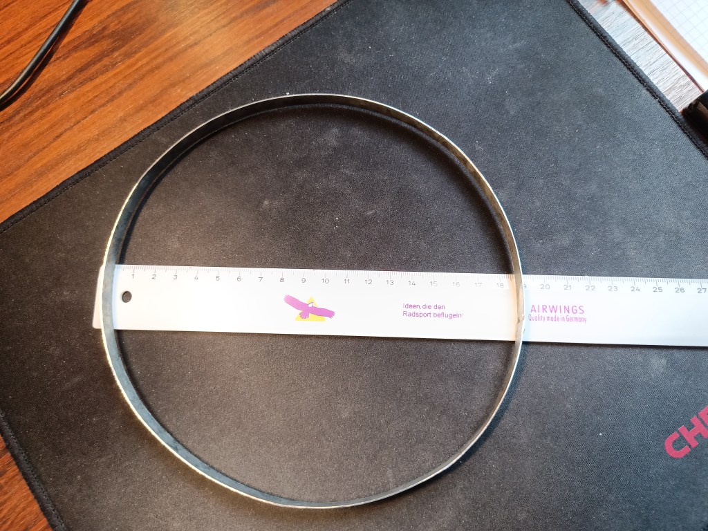
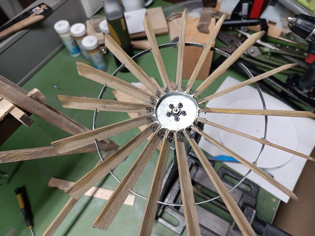
Schließlich habe ich einen weiteren Metallring angefertigt, um die mit filigranen Schräubchen befestigten, dünnen Holz-Rotorblätter zusätzlich zu stabilisieren.
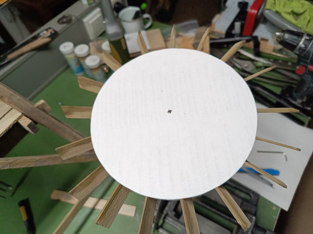
Den habe ich bis auf eine Breite von 5 mm heruntergeschliffen und in eingesägte Nuten der Flügelräder geklebt. Dazu hatte ich mir eine Papierschablone angefertigt, um die Positionen der Nuten festzulegen. Dieser Vorgang hatte das Flügelrad noch einmal deutlich stabilisiert.
Im nächsten Beitrag baue ich die Fundamentplatte und noch einige Anbauteile. Die Zeit bis zum Super Scale 2026 schwindet und ich habe noch einen kleinen Werkstattbau vor mir.
Wird schnellstmöglich fortgesetzt…
English Version
Wind-powered water pumping Part 2
Sources: Internet image search
We then moved on to the water supply construction site. First, three reinforcement straps were also fitted to the water tank. They are even equipped with screws and nuts to pre-tension the wooden planks.
The fittings on the pipes were added purely for aesthetic reasons. Two different methods were chosen for this. Both variants began with bending the pipe by 90 degrees. In one case, a pipe was pushed onto the pre-bent plastic rod and glued in place. This represents the expansion into which the pipe is screwed. Cast fittings usually have an additional reinforcement bead at the start of the thread. Pipe threads taper towards the rear and are almost metallically tight when fully screwed in. The reinforcement bead absorbs these forces. This bead was made from 1 mm drilled plastic scraps and glued on.
On the thicker pipe, the widening for the thread was filled with two layers of filler. Below are the unfinished parts again.
I used special flat and round files to remove the filler.
After painting, the first signs of rust appeared on the cut pipe threads. The result is shown below. The fill line from above and an overflow line.
I also installed a connecting sleeve in the fill line. The photo also shows the first results of the wood aging process.
To prevent the pipes from hanging freely in the room, I built a suitable mounting bracket. Narrow strips of sheet metal were shaped around the pipe on the left and right using flat-nose pliers. This resulted in the typical clamp shape for attaching pipes. A wood screw holds the bracket to the surface. Brass nuts M0.8 and matching screws hold the clamp halves together.
A crossbar was screwed to the floor in front of the water tank and serves as a bracket for the three clamps.
The wind vane was also slimmed down and lightened to achieve a balance with the rotor at the pivot point.
The base of the pivot bearing was also modified again. The 11/5 mm bearing initially used was replaced by a larger bearing measuring 30/10 mm. This allows the bearing to rotate more freely in the wind. The smaller bearing was under too much tension and impeded the rotational movement.
Finally, I made another metal ring to further stabilize the thin wooden rotor blades, which were attached with delicate screws.
I sanded it down to a width of 5 mm and glued it into grooves sawn into the wing wheels. I made a paper template to determine the positions of the grooves. This process significantly stabilized the impeller once again.
In the next post, I will build the base plate and a few more add-on parts. Time is running out until Super Scale 2026, and I still have a small workshop to build.
Will be continued as soon as possible…
Translation, with the kind support of deepl.com
