English Version
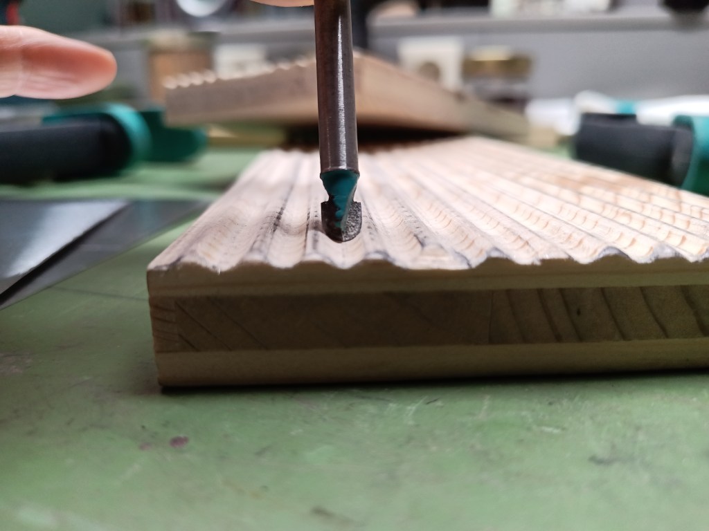
Der Bau meiner Hütte nähert sich so langsam dem Ziel. Nach dem Dach für die Veranda fehlte noch das Hauptdach. Es sollte mit Platten aus Wellblech verschlossen werden. Im Rahmen meiner ersten Versuche hatte ich schon ein Werkzeug dafür hergestellt und mit der Herstellung experimentiert. Mit einem 6 mm Halbrundfräser sind in zwei verleimte Bretter Mulden gefräst worden. Die Kanten wurden mit einem weiteren Fräser und Schmirgelleinen gebrochen.
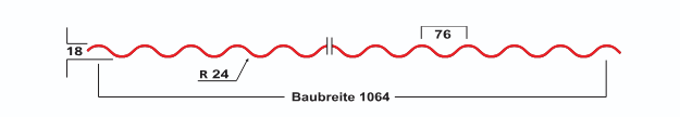
Die Originalmaße der Wellblechplatte 18/76:

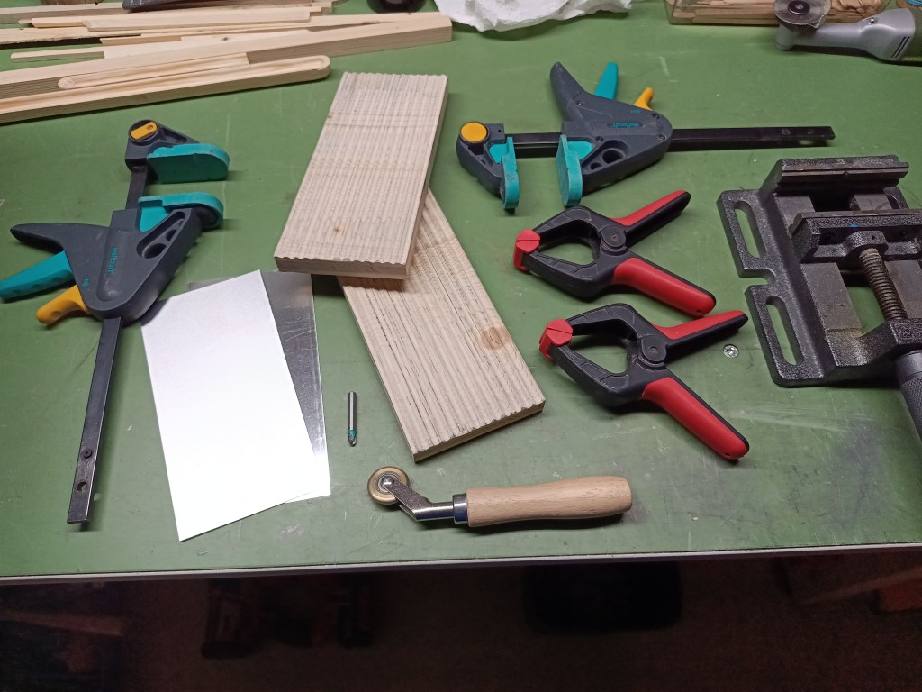
Nachfolgend alle Teile, die ich zur Herstellung der Wellblechplatten benötigte. Für die Platten habe ich mich an der Standardbreite von 1120/1064 mm orientiert. Da ich nur Aluminiumplatten im 200 mm Raster zur Verfügung hatte, bin ich hier aus Effizienzgründen auf eine Breite von 100 mm gegangen. Die Länge habe ich auch an der Plattengröße ausgerichtet, also 200 mm x 100 mm (Länge x Breite).
Eine Aluminium-Platte wurde an der ersten abfallenden Welle angelegt und auf der Gegenseite fixiert. Im nächsten Schritt folgen zwei Prägungen mit der Andruckrolle. Das Material wölbt sich dabei nach oben.
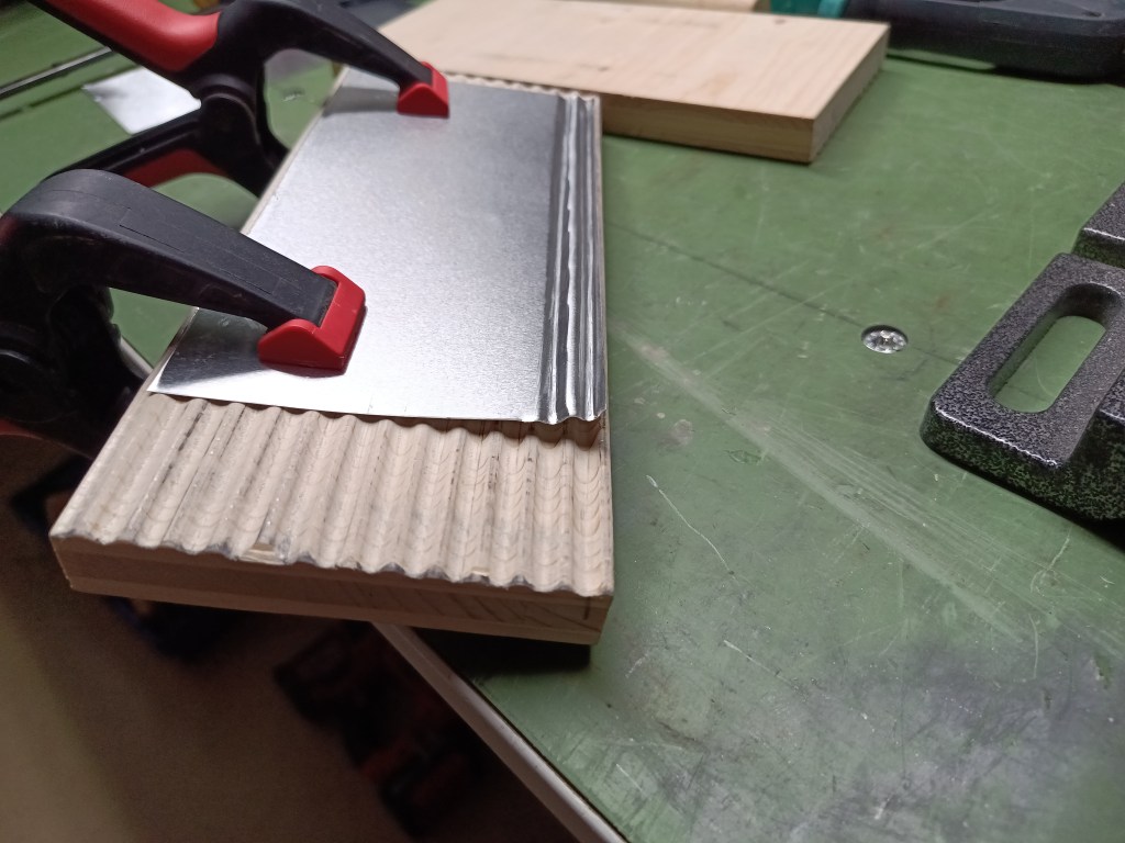
Um das Blech in seiner Form zu halten, wurde die erste Mulde mit einem Gewicht auf der Schablone belastet.
Die Andruckrolle, möglichst senkrecht und unter Druck, mit kleinen Vor- und Rückwärts-Rollbewegungen nun das Aluminium in die Holzstruktur einprägen. Das Blech streckte sich dadurch in die Mulde und wird so auch dünner. Daher es bitte nicht mit dem Rollen übertreiben. Ist das Profil sauber vorhanden, den Vorgang beenden. 0,3 mm Wandstärke lassen nur bedingte Spielräume. Das Ergebnis wird nur so gut, wie die aus dem Holz herausgearbeitete Struktur. Schwächen in der Vorarbeit wären daher nun auch sichtbar. Die Andruckrolle ist auch ein käufliches Produkt, dessen Breite nicht perfekt meine 6 mm Mulde ausfüllte. Daher meine Empfehlung die Rolle immer senkrecht und mit Nachdruck zu führen.
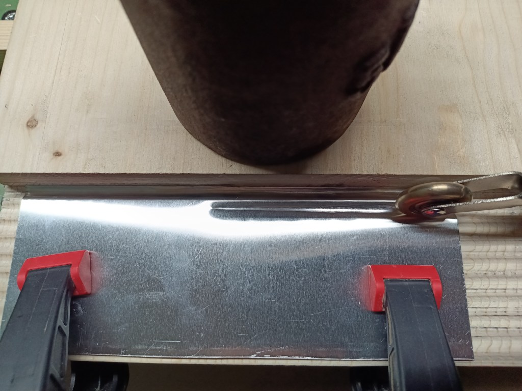
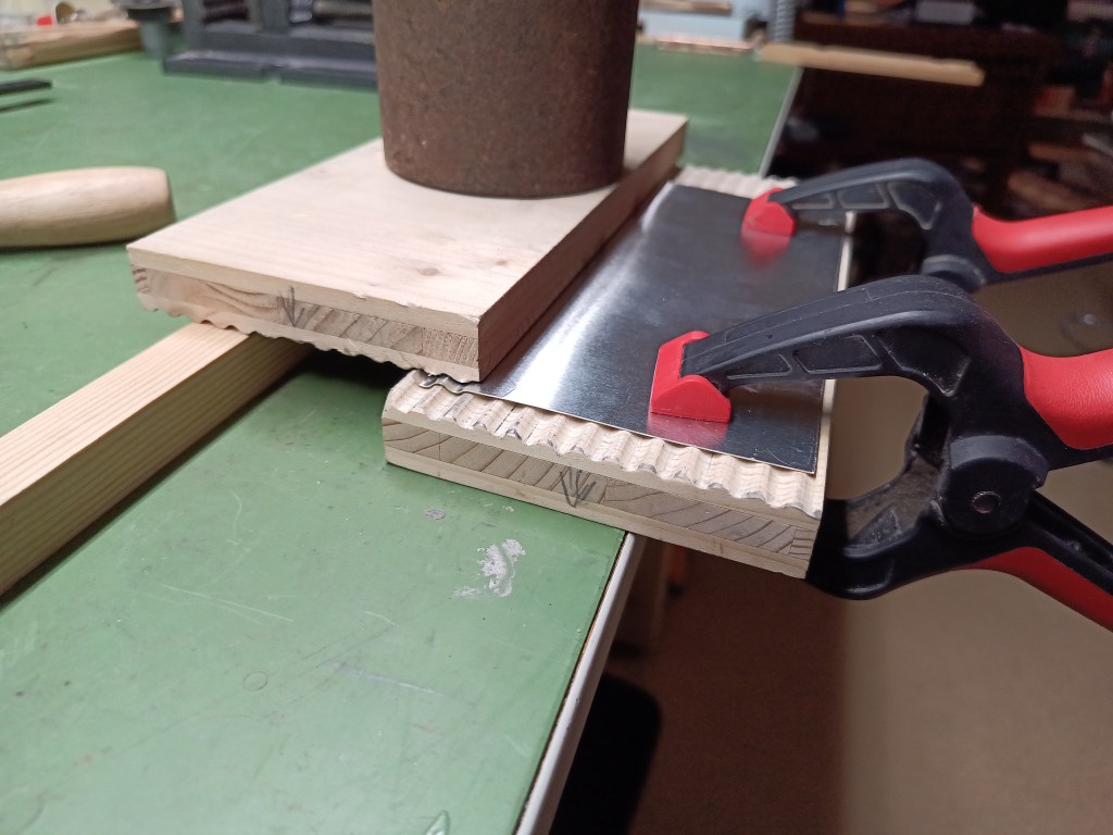
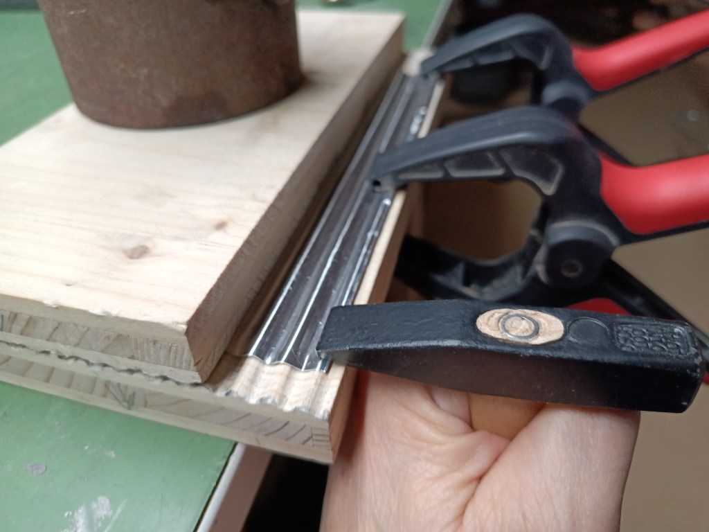
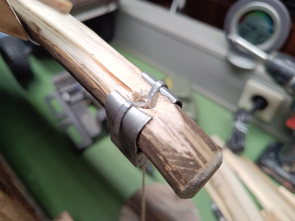
Nach jeder geprägten Rille wurde das obere Gegenprofil eine Mulde weitergeschoben und beschwert. Es folgte dann die nächste Prägung und ein erneutes Umsetzen des Gegenprofiles, Zug um Zug, bis zum Ende des Aluminiumbleches. Der schmale Grat am Ende der Platte hat nun auch wieder die Tendenz sich aufzurollen. Mit einem Werkzeug, hier eine Hammerfinne, diesen Rand mechanisch umformen.
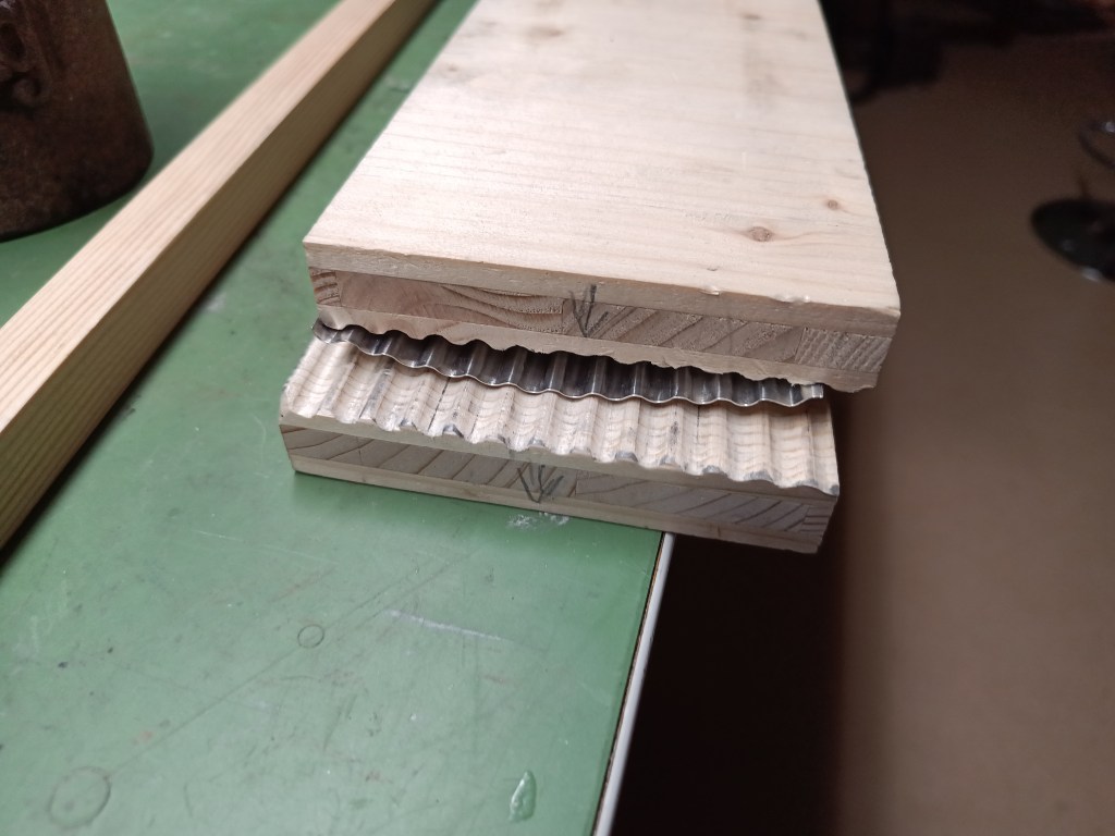
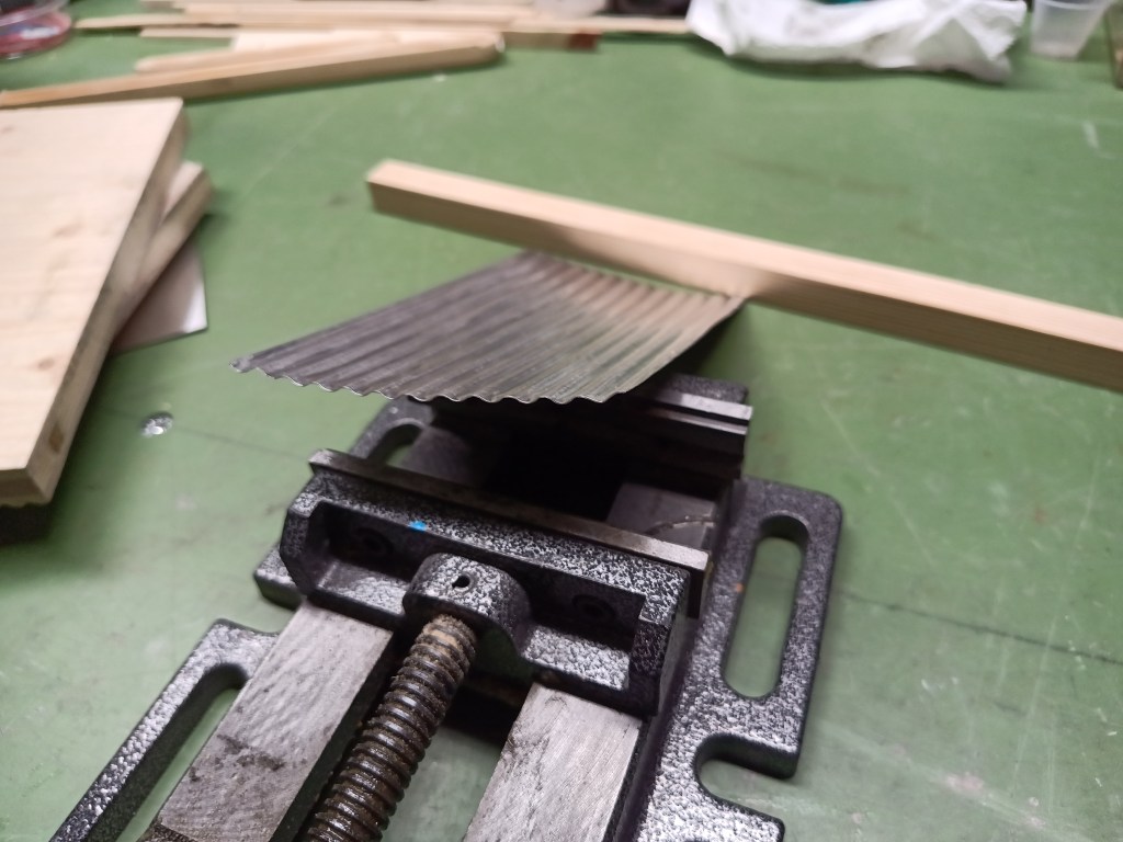
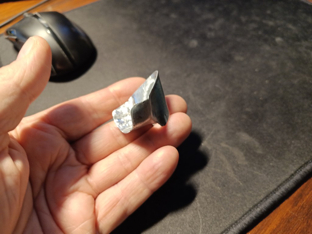
Mit dem so geprägten Blech zwischen den beiden unbelasteten Prägestempeln, sieht das dann etwa so aus. Durch die nicht immer gleich hohen Druckkräfte und die Rollbewegungen ist das Wellblech leicht verspannt und entsprechend verformt.
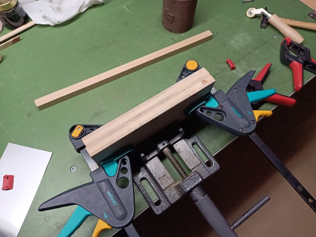
Mit Zwingen und im Schraubstock gab es jetzt noch etwas Druck auf das Blech.
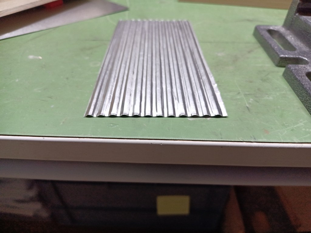
Links dann das Ergebnis nach der Pressung, noch etwas verspannt und rechts mit den Händen gefühlvoll gerichtet. Bereit für den Einbau.
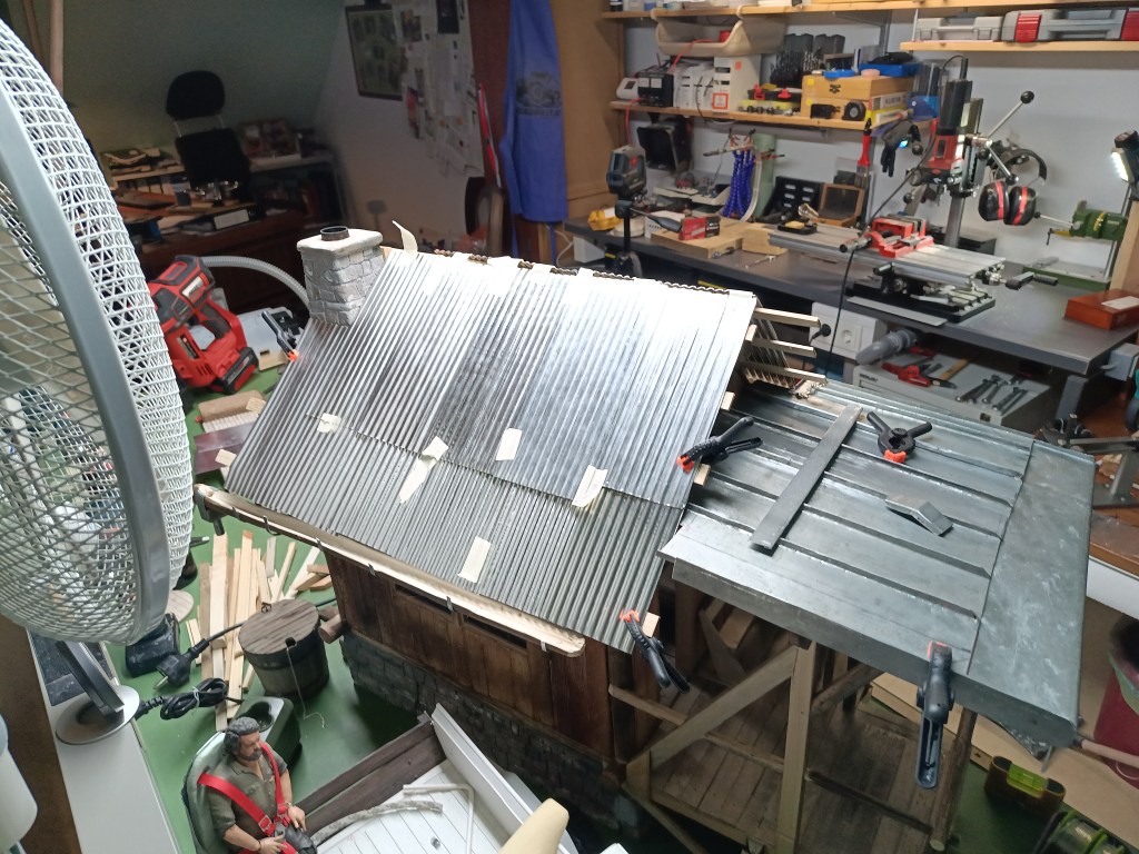
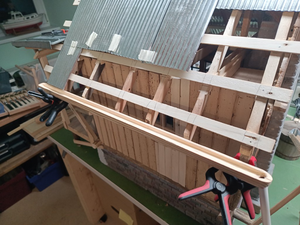
Nach einigen Stündchen, dann ein erstes hoffnungsvolles Bild. Die erste Dachseite ist hergestellt und provisorisch befestigt. Wie zu sehen ist, wird das Ergebnis trotz gewisser Unzulänglichkeiten akzeptabel. Angesichts der noch folgenden Alterung und Verformungen, ja geradezu perfekt. Das Dach der Veranda wurde nun auch ausgespart.
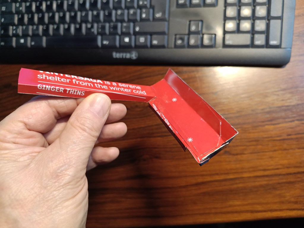
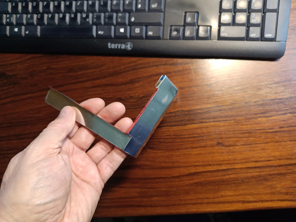
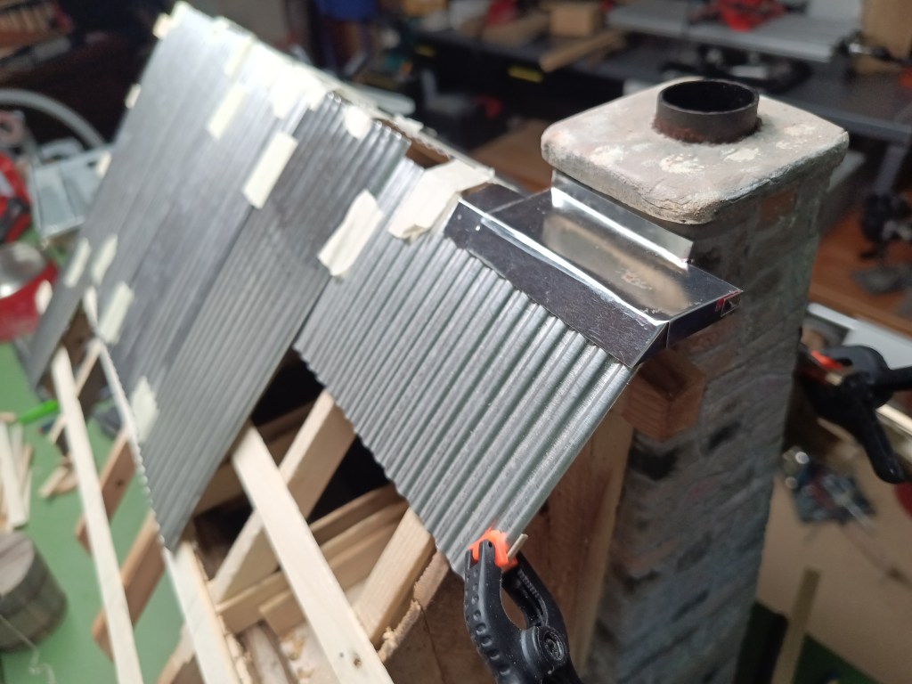
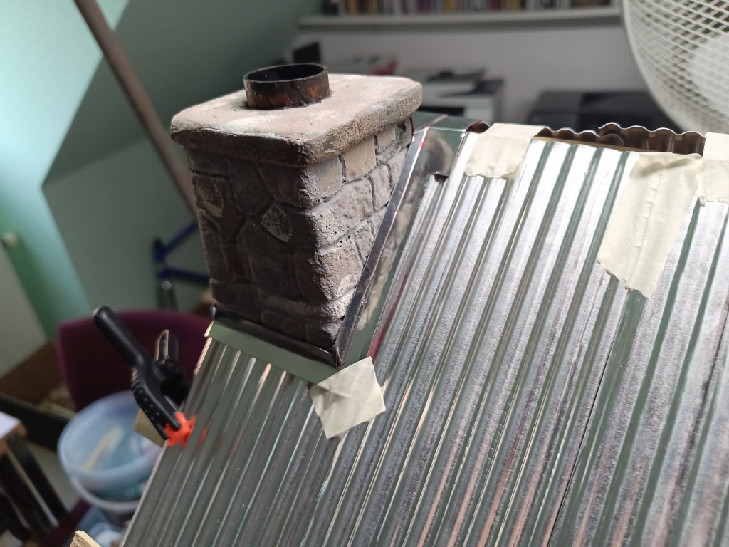
Aus dem Stahlblech einer Keksdose hatte ich die Kamineinfassung hergestellt. Die einzelnen Blechteile wurden nach der Umformung entfettet und mit Sekundenkleber verklebt. Sie sollen später den Wassereintritt ins Gebäude verhindern. Dazu werden die Blechstege noch mit Silikon an den Kamin geklebt.
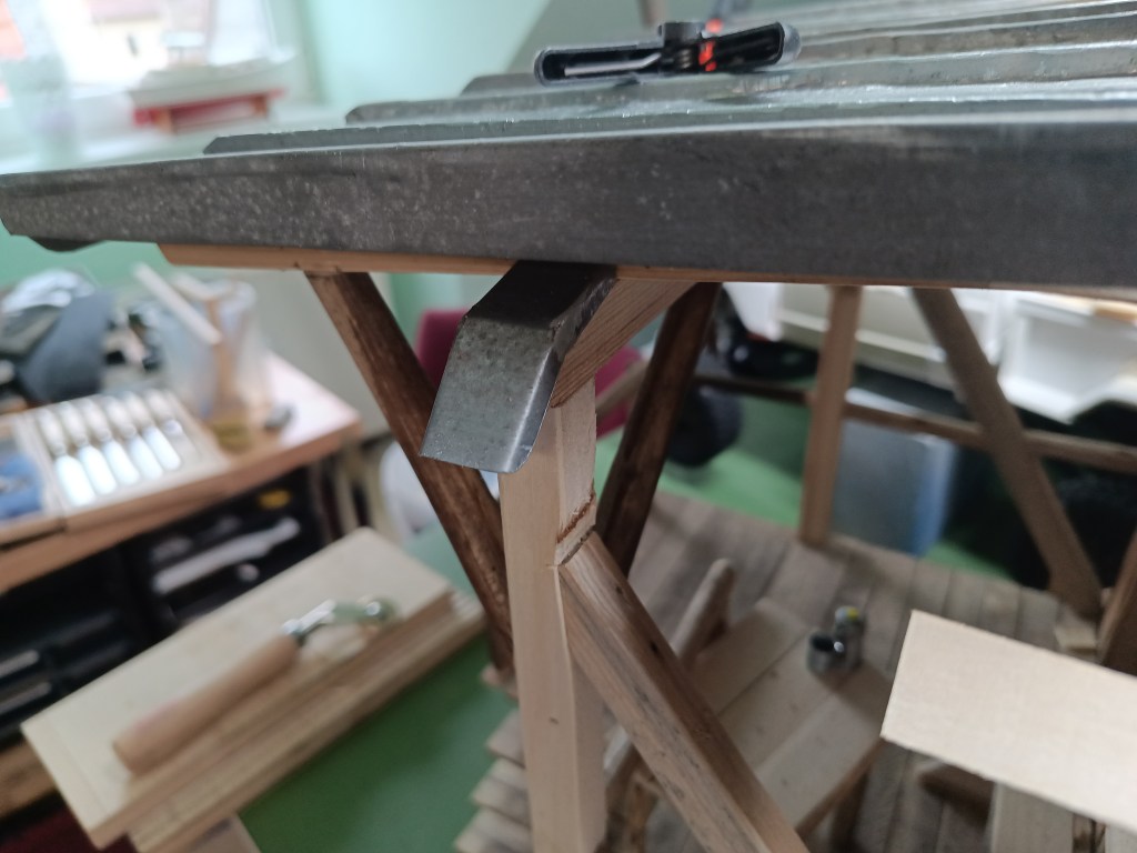
Ein unter dem Verandadach überstehender Balken erhielt noch eine Blechabdeckung, um Feuchtigkeitsschäden zu verhindern.
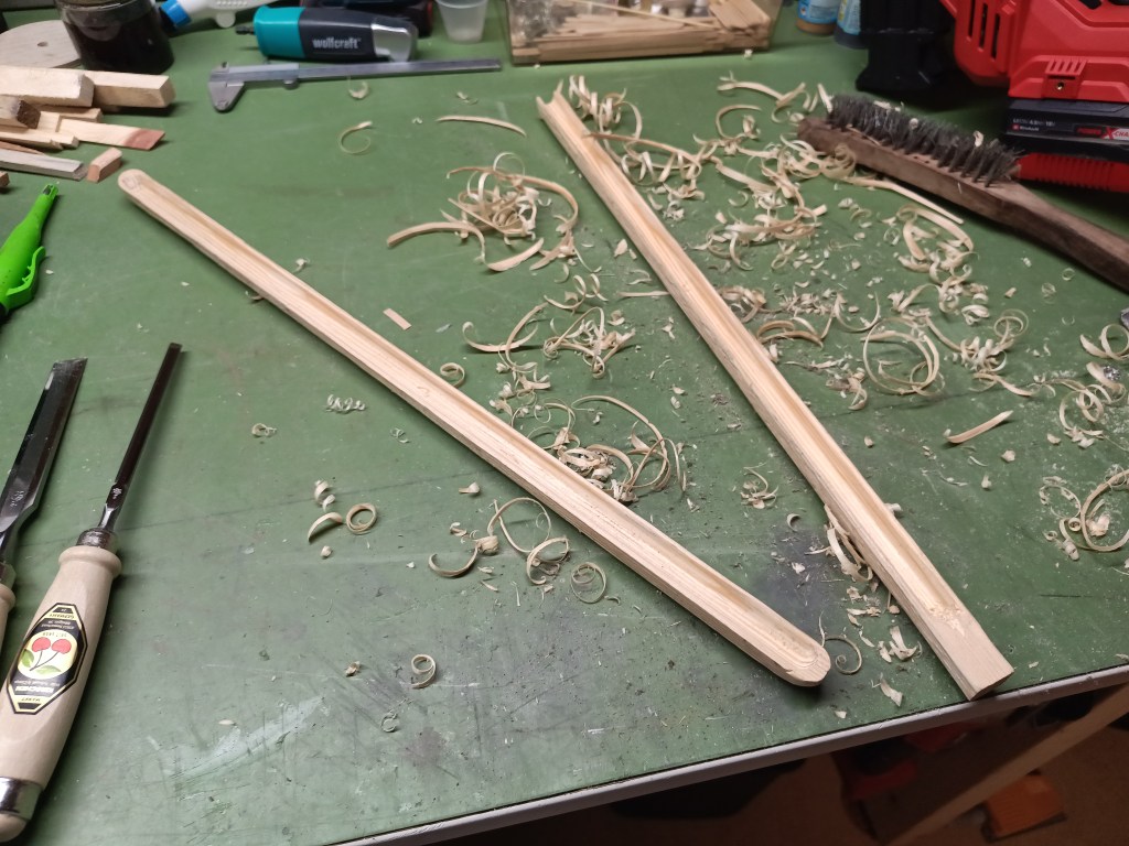
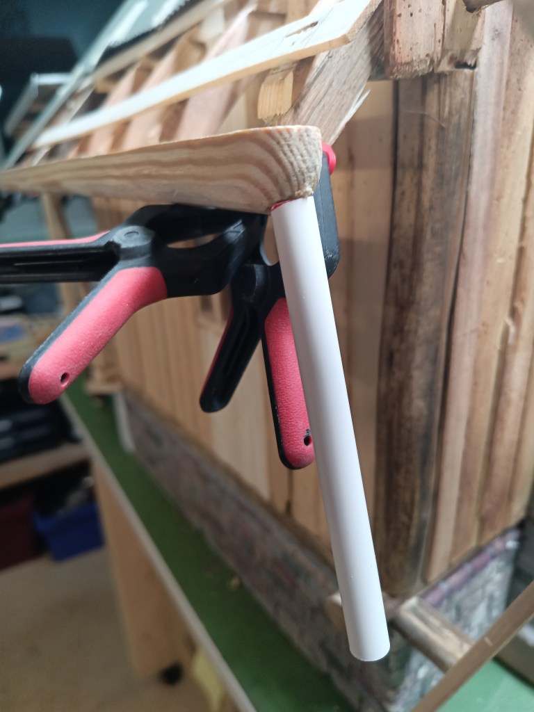
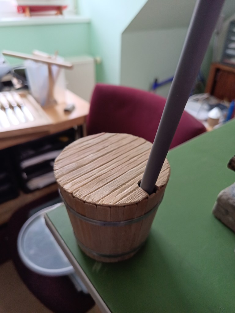
Die hintere Regenrinne wurde aus einem 4-kant-Holz rund geschnitzt. Mit einem Fräser die Ablaufmulde herausgearbeitet. Ein Holzdübel 8 mm wurde mit einem Bohrer 6 mm durchbohrt und in den Ablauf der Regenrinne eingeklebt. Dann ein Kunststoffrohr 10 mm aufgesteckt. Es verlängert nicht nur den Ablauf, sondern stabilisiert auch den dünnwandigen Holzdübel, wegen der Bohrung.
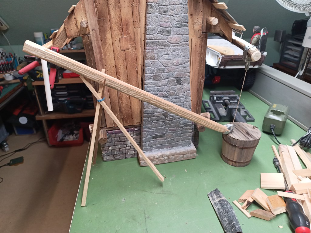
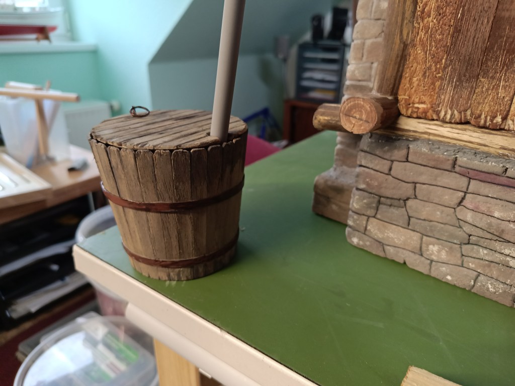
Das ablaufende Wasser wird dann quer hinter dem Gebäude vorbeigeführt und im bereits gebauten Regenfass zusammengeführt.
Das Wasserfass hatte inzwischen die Optik auch stark verändert und ist um Jahre gealtert.
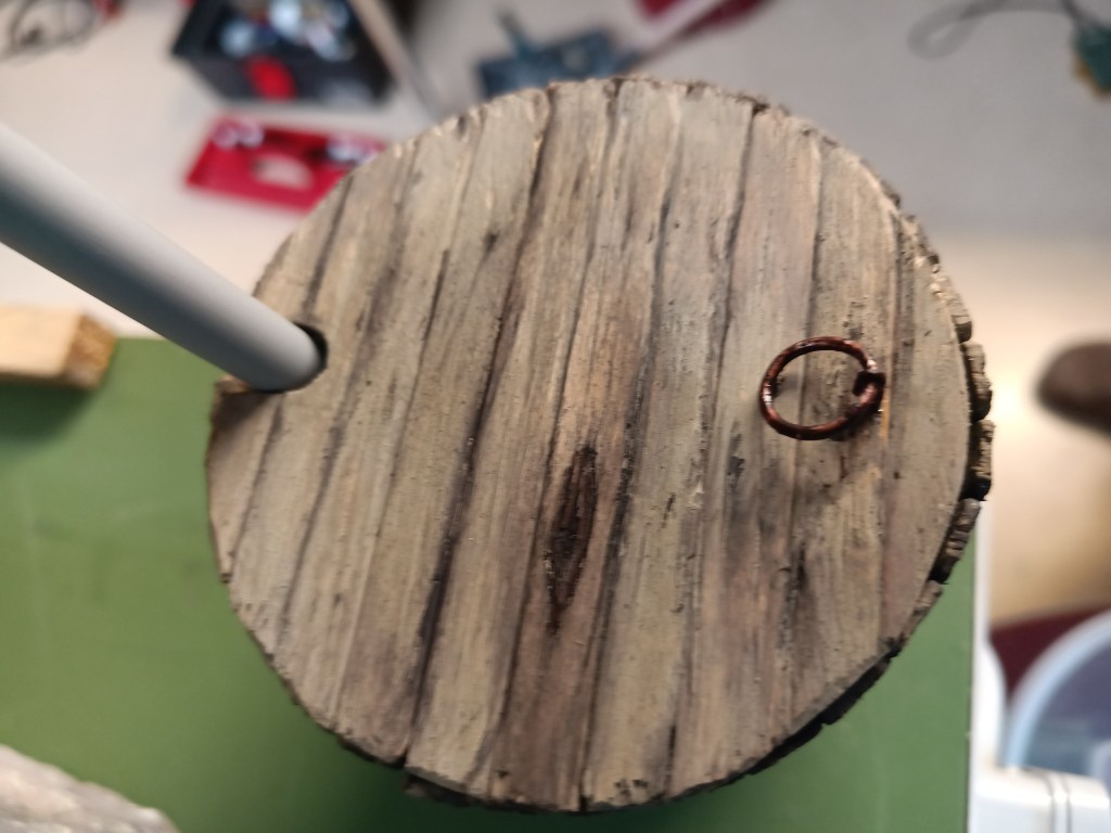
Das ursprünglich dort geplante Abflussrohr wurde durch eine Kette ersetzt. Modeschmuck aus der Schatulle meiner Frau, schien dazu mehr als geeignet. Ist sie erst einmal verrostet, wird man ihr den Ursprung nicht mehr ansehen. Und noch deutlich günstiger, als beispielsweise Ketten aus dem Bereich Schiffsmodellbau. Ein Haken hält die Kette oben im Einlaufkasten fest.
In diesem kleinen, aus Blechresten, zusammengelöteten Trichter findet das Wasser schließlich zusammen.
Nun werde ich die fehlenden Dachplatten noch herstellen und mit der Alterung des Daches beginnen. Ergebnisse dann in einem der nächsten Beiträge.
Wird schnellstmöglich fortgesetzt…
English Version
How to build a model house roof from corrugated iron sheets
The construction of my cabin is slowly nearing completion. After finishing the roof for the porch, the main roof was still missing. It was to be covered with corrugated iron sheets. As part of my initial experiments, I had already made a tool for this and experimented with the manufacturing process. Using a 6 mm half-round cutter, I milled grooves into two glued boards. The edges were broken with another cutter and emery cloth.
The original dimensions of the corrugated sheet metal panel 18/76:
Below are all the parts I needed to make the corrugated iron sheets. For the sheets, I used the standard width of 1120/1064 mm as a guide. Since I only had aluminum sheets available in 200 mm increments, I opted for a width of 100 mm for efficiency reasons. I also based the length on the sheet size, i.e., 200 mm x 100 mm (length x width).
An aluminum sheet was placed on the first sloping wave and fixed on the opposite side. The next step involves two embossings with the pressure roller. This causes the material to curve upward.
To keep the sheet metal in shape, the first trough was weighted down with a weight on the template.
Using the pressure roller, as vertically as possible and under pressure, press the aluminum into the wood structure with small forward and backward rolling movements. This causes the sheet metal to stretch into the hollow and become thinner. Therefore, please do not overdo it with the roller. Once the profile is clean, stop the process. A wall thickness of 0.3 mm allows only limited leeway. The result will only be as good as the structure carved out of the wood. Any weaknesses in the preparatory work would therefore now also be visible. The pressure roller is also a commercially available product, the width of which did not perfectly fill my 6 mm hollow. Therefore, I recommend always guiding the roller vertically and with pressure.
After each embossed groove, the upper counter profile was moved one hollow further and weighted down. This was followed by the next embossing and another repositioning of the counter profile, step by step, until the end of the aluminum sheet. The narrow ridge at the end of the plate now also has a tendency to curl up again. Use a tool, in this case a hammer fin, to mechanically reshape this edge.
With the embossed sheet between the two unloaded embossing stamps, it looks something like this. Due to the pressure forces not always being the same and the rolling movements, the corrugated sheet is slightly warped and deformed accordingly.
With clamps and in a vise, there was now a little more pressure on the sheet.
On the left, the result after pressing, still a little tense, and on the right, carefully adjusted by hand. Ready for installation.
After a few hours, a first hopeful picture. The first side of the roof has been made and provisionally attached. As you can see, the result is acceptable despite certain shortcomings. In view of the aging and deformation that is still to come, it is downright perfect. The roof of the veranda has now also been recessed.
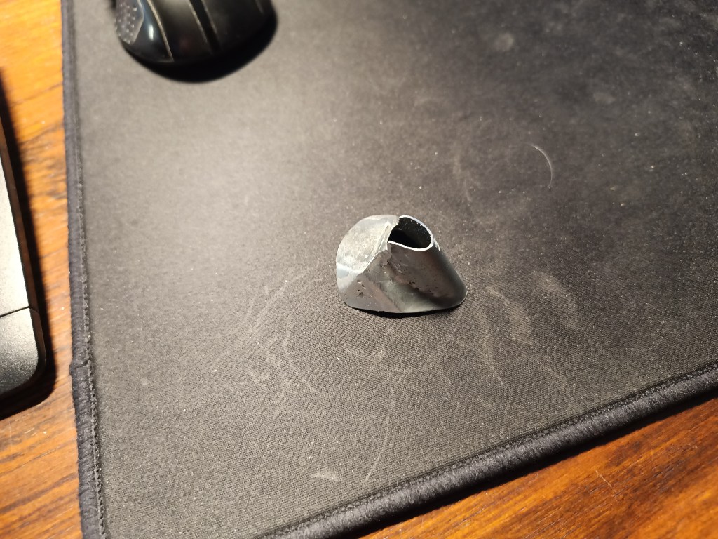
I made the chimney surround from the sheet steel of a cookie tin. After forming, the individual sheet metal parts were degreased and glued with superglue. They will later prevent water from entering the building. For this purpose, the sheet metal strips are glued to the chimney with silicone.
A beam protruding from under the porch roof was covered with sheet metal to prevent moisture damage.
The rear rain gutter was carved from a square piece of wood. The drainage trough was carved out with a milling cutter. An 8 mm wooden dowel was drilled through with a 6 mm drill bit and glued into the drain of the rain gutter. Then a 10 mm plastic pipe was attached. This not only extends the drain, but also stabilizes the thin-walled wooden dowel due to the hole.
The runoff water is then directed across the back of the building and collected in the rain barrel that has already been built.
The water barrel had also changed significantly in appearance and looked years older.
The drain pipe originally planned for this location was replaced by a chain. Costume jewelry from my wife’s jewelry box seemed more than suitable for this purpose. Once it has rusted, its origin will no longer be apparent. And it is even cheaper than chains used in ship model building, for example. A hook holds the chain in place at the top of the inlet box.
The water finally collects in this small funnel, which is soldered together from scrap metal.
Now I will make the missing roof tiles and start aging the roof. I will share the results in one of my next posts.
Will be continued as soon as possible…
Translation, with the kind support of deepl.com
