English Version
Wer kennt das nicht? Eine zunächst überschaubare Baustelle entwickelt sich zum Gegenteil. So ist auch meinem teilweise, provisorischen Lichtausbau viel weitere Arbeit gefolgt.
Das alles funktioniert war mir wieder einmal nicht gut genug. So war schon beim Bauen klar, dass die Kabelverbindung der Rücklichter, mit der am Rahmen verschraubten Stoßstange, kein Dauerzustand sein kann. Ohne vorherige Erfahrungen, war meine angedachte Lösung kein einfaches Unterfangen. Die einfachste Lösung, eine Steckverbindung, scheiterte aus praktikablen Gründen. Beim Absetzen der bisher mit dem Rahmen verschraubten Karosserie, müsste das Auto auf dem Dach liegen. Damit hätte ich auch kein Problem, nur es gibt inzwischen kein Dach mehr. Das fahrfertige Model wiegt mit Stoffdach 4,3 kg. Einfach zu viel, um es auf dem filigranen Hilfsrahmen des Stoffdaches abzulegen. Wird dann noch daran gearbeitet, entstehen punktuell noch zusätzliche Lasten.
Daraus entstanden zwei Baustellen. Das werkzeuglose Abnehmen der Karosserie und gleichzeitiges Trennen der Kontaktstellen, zwischen Fahrzeugunterboden und Rahmen. Dafür kamen nach meiner Einschätzung nur Magnete in Frage. FMS hat auch hier wieder gute Vorarbeit geleistet.
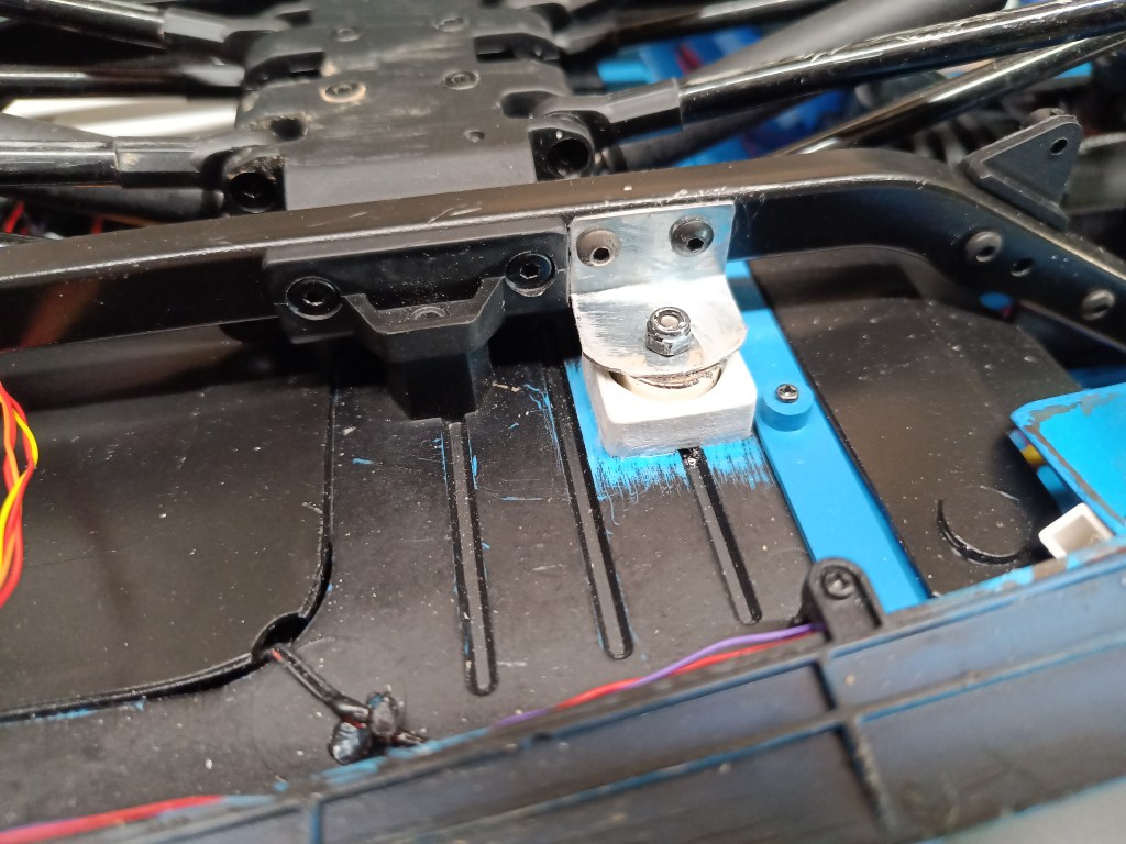
Sechs Schrauben M3, je zwei vorne, in der Mitte und hinten sorgen für eine perfekte Fixierung. Meine Variante sollte mit zwei Magnetpaaren in der Fahrzeugmitte funktionieren, Haltekraft 2×4 kg. Links im Bild die Original-Schraubbefestigung. Rechts meine Aufnahme, in der ein Magnet verklebt ist. Ein am Rahmen verschraubter Metallwinkel nimmt das rahmenfeste Gegenstück auf. Das Magnetpaar ist als Süd- und Nordpol ausgelegt, um sich perfekt anzuziehen.
Auch die vorderen Schrauben sind entfallen und haben nur noch zwei M3 Madenschrauben, um den Vorderbau sicherheitshalber in Flucht zu halten.
Sie finden ihr Gegenstück im Motorraum. Man sieht die dort schon vorhandenen Senkungen, unmittelbar vor dem Lenk-Servo. Die Madenschrauben wären damit eigentlich überflüssig, haben aber so noch eine Funktion als Zentrierhilfe und zusätzliche Führung.

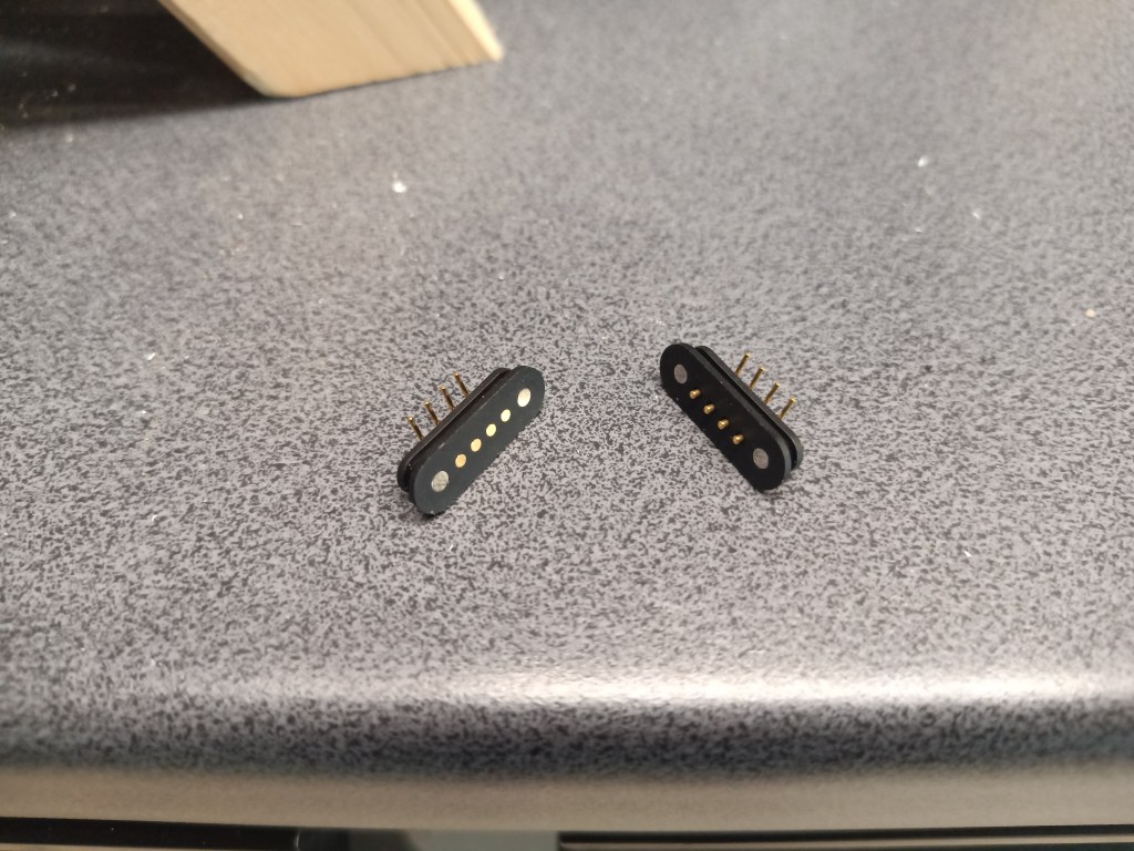
So an zwei Punkten fixiert, konnte es mit der Schlüsselstelle weitergehen. Dazu hatte ich zwei Kontakt-Varianten bestellt. Links eine Ausführung mit integrierten Magneten und rechts nur mit beidseitiger Kontaktierung. Meine Entscheidung fiel auf die linke Ausführung mit den integrierten Magneten. Letztlich auch wegen der Möglichkeit, die Kabel steckbar zu montieren.
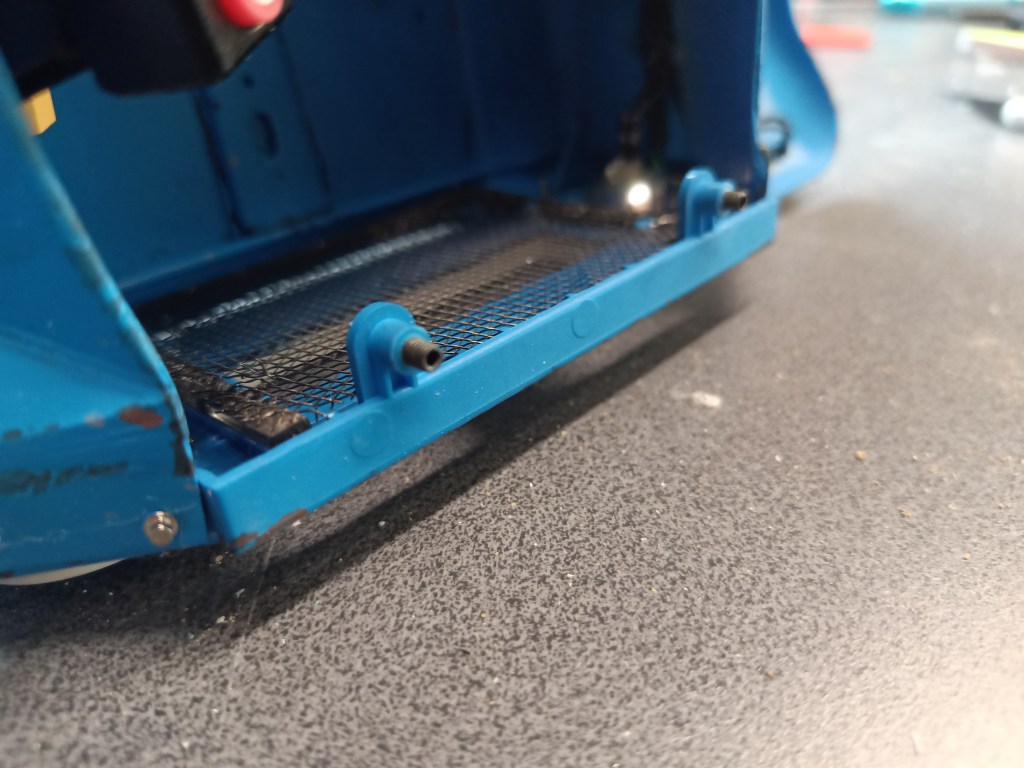
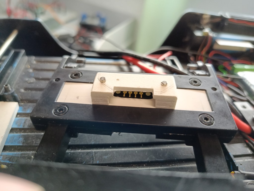
Die Verbindung sollte in eine der hinteren Aussparungen eingebaut werden, direkt neben der Schaubbefestigung. Nachfolgend sieht man den Aufbau des am Unterboden verklebten Kontaktpunktes. Auch hier sichtbar, die zwei Madenschrauben M3. Diese Kontaktstelle passt in das Gegenstück im Rahmenprofil. So entsteht eine formschlüssige Halterung, die gleichzeitig auch Kontaktbrücke ist. Um die Wirkung der Magnete nicht einzuschränken, habe ich die beiden Bohrungen in der Kontaktplatte nachträglich noch vergrößert. Das so entstandene horizontale Spiel sichert eine beständige Kontaktierung. Starr verschraubt, kam es zu vereinzelten Lichtunterbrechungen. Die nur einen Millimeter kleinen Kontaktpunkte verzeihen keinen Versatz oder Verspannung. Da habe ich nicht exakt genug gemessen und gearbeitet.

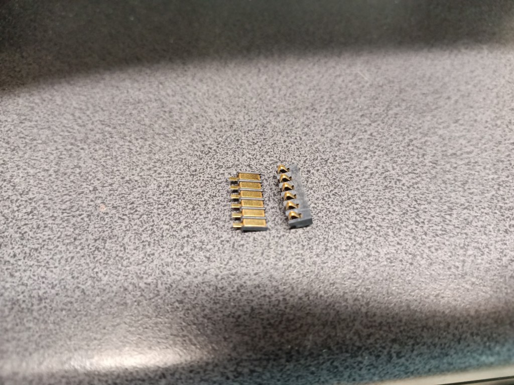
Das Gegenstück ist im Rahmenprofil verschraubt. Hier schon mit der Schutzabdeckung für die Kontakte, aber noch ohne Befestigung am Rahmen.
Hier noch einmal der Gesamtaufbau mit allen verbauten Teilen.

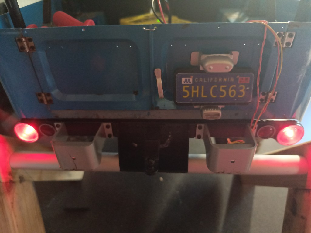
Eingebaut und mit externer Stromeinspeisung das Ergebnis. Es sieht wunderbar aus und funktioniert auch wie gewünscht, hat aber mit allem Messen und Versuchen fast vier Tage Arbeit gekostet. 😎
Inzwischen sind auch alle Teile schwarz lackiert und ich verlege jetzt noch diesen letzten Kabelstrang zum Lichtmodul. 😍
Wird schnellstmöglich fortgesetzt…
English Version
Let there be light, the final steps
Who hasn’t experienced this? An initially manageable construction site can quickly become unmanageable. My partial, provisional lighting installation was followed by a lot more work.
Once again, things didn’t work out the way I wanted them to. During construction, it was clear that the cable connection between the rear lights and the bumper bolted to the frame could not be a permanent solution. Without any prior experience, implementing my idea was no easy task. The simplest solution, a plug-in connection, failed for practical reasons. If the body, which had been bolted to the frame previously, was lowered, the car would have to lie on its roof. I wouldn’t have a problem with that, but there is no longer a roof. The ready-to-drive model weighs 4.3 kg with the fabric roof. That’s simply too much weight for the delicate subframe of the fabric roof. If work is carried out on it, additional loads are created at certain points.
This results in two construction sites. The bodywork can be removed without tools and the contact points between the vehicle underbody and the frame can be separated simultaneously. In my opinion, magnets were the only suitable option for this. Once again, FMS did a good job.
Six M3 screws—two at the front, two in the middle, and two at the rear—ensure perfect fixation. My version should work with two pairs of magnets in the middle of the vehicle with a holding force of 2×4 kg. The picture on the left shows the original screw fastening. On the right is my mount, which has a glued-on magnet. A metal bracket screwed to the frame holds the counterpart mounted to the frame. The pair of magnets is designed with north and south poles that attract each other perfectly.
For safety reasons, the front screws have been omitted and are now held in place by two M3 grub screws.
These screws have counterparts in the engine compartment. The countersinks are already present there, directly in front of the steering servo. While the grub screws are superfluous, they still serve as a centering aid and additional guide.
With these two points fixed, it was possible to move on to the next step. For this, I had ordered two contact variants. One version had integrated magnets, and the other had contacting on both sides. I chose the left version with integrated magnets. This was ultimately also because of the option of plugging in the cables.
The connection should be installed in one of the rear recesses directly next to the screw fastener. The structure of the contact point glued to the underbody is shown below. The two M3 grub screws are also visible. This contact point fits into its counterpart in the frame profile. This creates a form-fit mounting that also serves as a contact bridge. To avoid restricting the effect of the magnets, I enlarged the two holes in the contact plate. The resulting horizontal play ensures consistent contact. When rigidly screwed in, there were occasional interruptions in the light. The contact points, which are only one millimeter in size, do not allow for any misalignment or distortion. I did not measure and work precisely enough.
The counterpart is screwed into the frame profile. This picture shows it with the protective cover for the contacts, but not yet attached to the frame.
Here is the complete assembly once again, with all installed parts.
Here is the result with the external power supply after installation. It looks wonderful and works as desired, but it took almost four days of work, including all the measuring and testing. 😎
In the meantime, I have painted all the parts black, and I am now laying the last cable harness to the light module. 😍
Will be continued as soon as possible…
Translation, with the kind support of deepl.com
