English Version
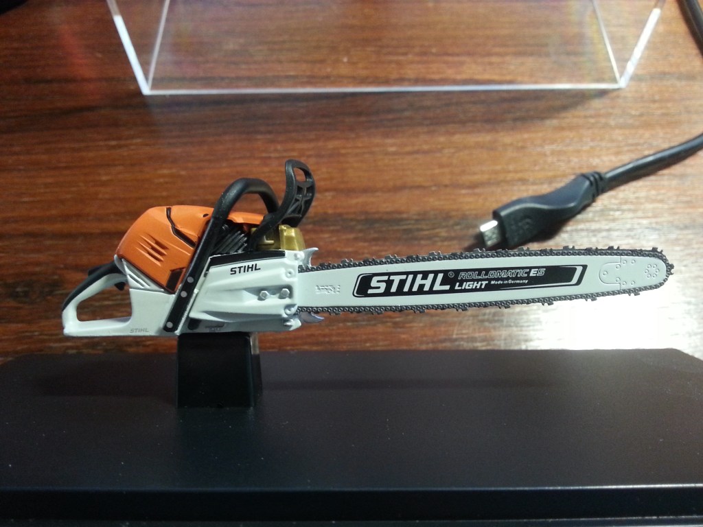
Im heutigen Beitrag geht es um den Bau einer Kettensäge. Sie wird ein Ausstattungsdetail der Werkstatt auf dem SuperScale 2026 werden. Es gibt in meinem Fundus schon ein hochwertiges und fein detailliertes Modell der Stihl M500i.
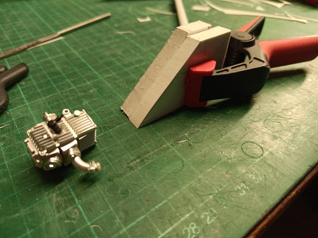
Die wäre aber für das geplante Urwaldhaus auf dem SuperScale 2026 viel zu schade. Mein Wettbewerbsbeitrag ist ja eine Urwaldhütte mit Wellblechdach. Ein Teil des Geländes soll eine Steinmauer bekommen, an dem eine kleine überdachte Werkstatt angebaut werden soll. Ein strammes Bauprogramm im Jahr 2025 steht somit schon fest. Nun zum Bau der Säge. Sie hat kein Vorbild in der Realität und wird von einem 4-Takt-Motor angetrieben. Das Kurbelgehäuse ist ein Eigenbau, wie auch alles rund um die Urwaldsäge. Kreativität wird wieder einmal im Vordergrund stehen. Also los. Aus Forex Resten wurden zwei Blöcke geschnitten und zusammengeklebt. Im Vordergrund der zweckentfremdete Zylinder einer Honda Monkey.
Erste Konturen wurden aus dem Block gefräst und geschnitzt. So ist aber noch zu viel Material an der Monstersäge.
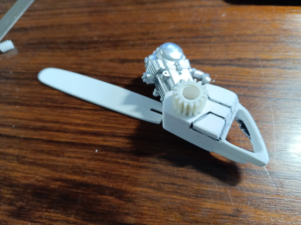
Etwas filigraner wäre schon wünschenswert. Also weiter abspecken. Die Konturen von Kraftstoff- und Kettenöl-Tank wurden abgesetzt und farbig konturiert, um die Proportionen zu beurteilen.
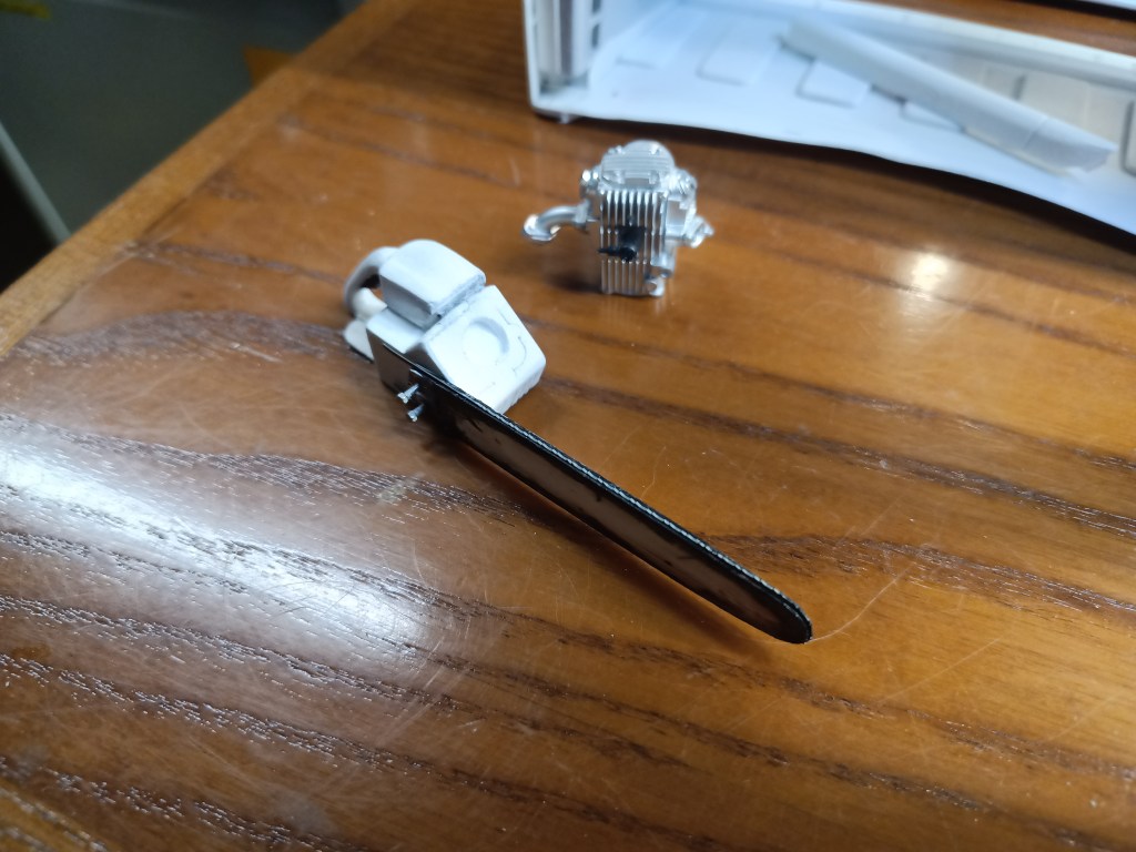
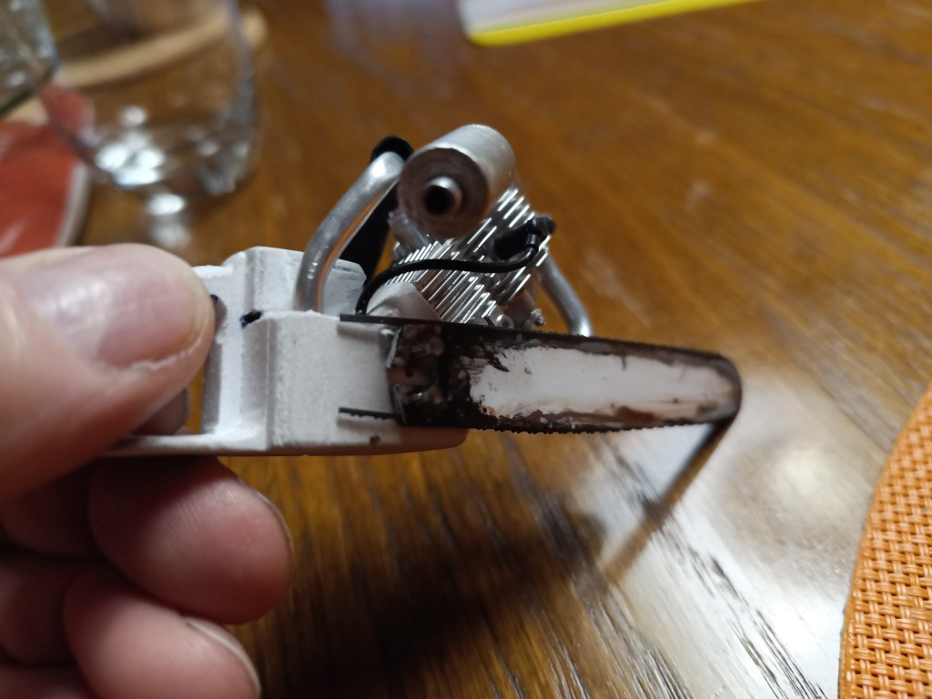
Das Schwert ist dreilagig mit einem minimal kleineren Mittelteil. So klein das ein Laubsägeblatt noch sichtbar darin liegen kann. Die wurden in vielen Versuchen kalt gebogen. Sägeblätter sind in der Regel gehärtet und somit alles andere als biegefreundlich. Mein Vorrat wurde daher etwas dezimiert. Oben im Bild ein gelungener Versuch.
Das fehlende untere Teil wurde aus einem Bruchrest angestückelt. Es fällt auch später nicht mehr auf, solange keine Lupe ins Spiel kommt. Verklebt mit Sekundenkleber.
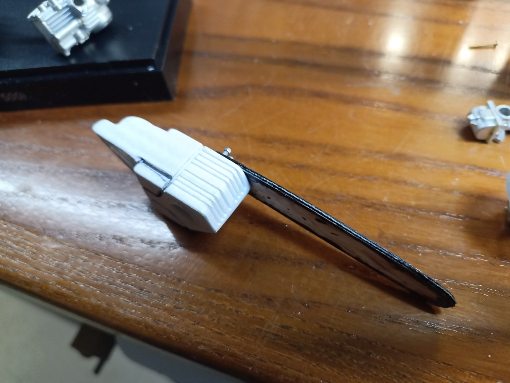
Das Schwert wurde auch sogleich mit ersten Gebrauchspuren versehen. Die werden nach der Trocknung noch auch etwas nachgearbeitet.
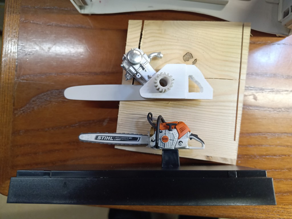
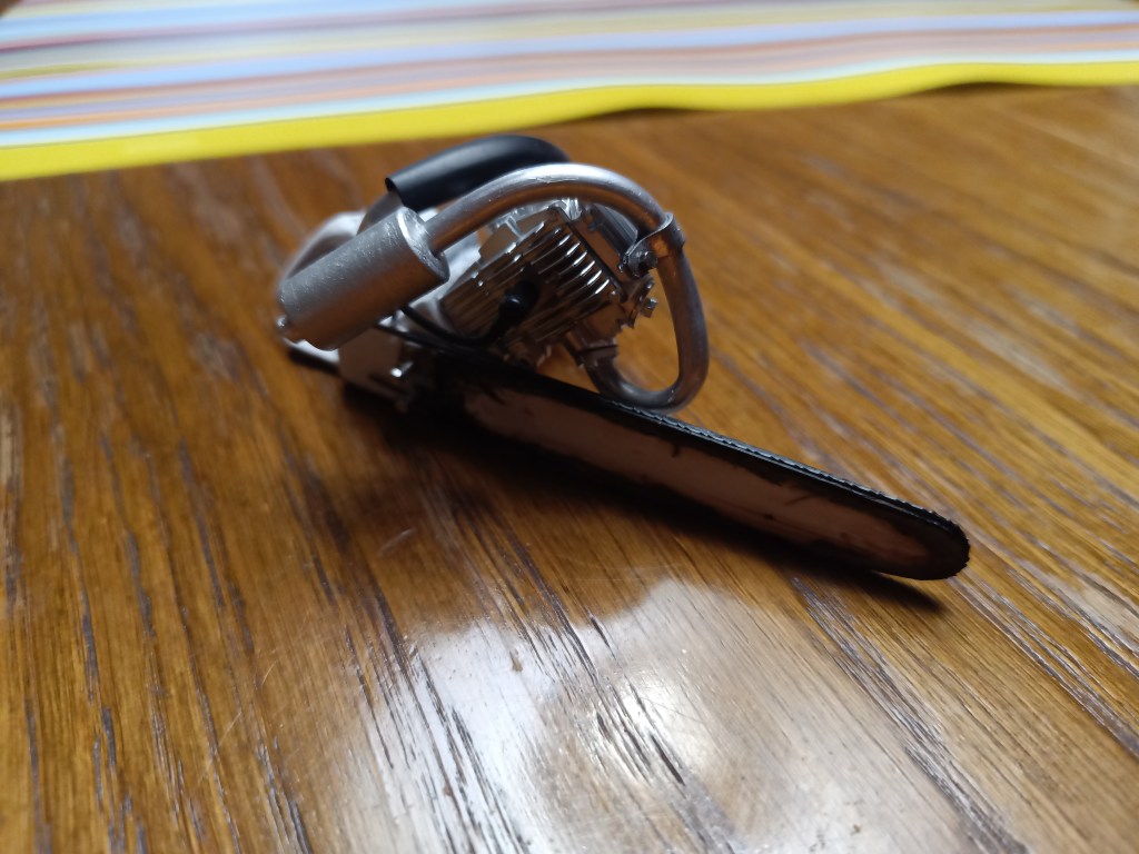
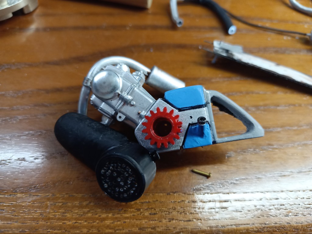
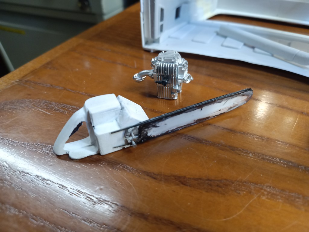
Bevor es mit den Abdeckungen der Sägekette und des Kühlgebläses weitergeht, der vorläufige Baustand. So ein 4-Takter ist etwas größer und passt doch auch gut zum filigranen Stihl Original. Beides im Maßstab 1:10.

Ins Kurbelgehäuse wurden noch einige Kühlrippen eingefräst…
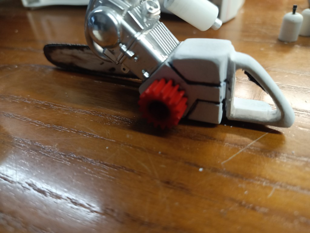
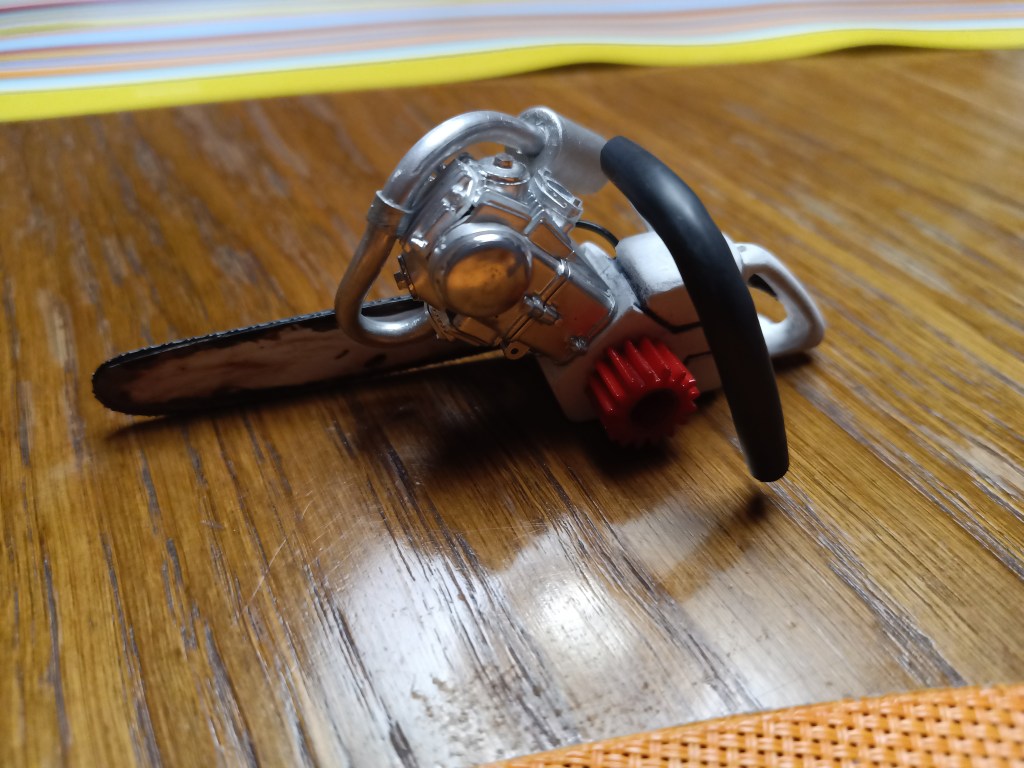
…und das Kühlgebläse rot angelegt.
Aus 4 mm Aluminiumrohr weich, wurde ein enger Bogen als Abgasanlage geformt. Der Schalldämpfer entstand aus zwei ineinander geschobenen Rohrstücken. Als Abschlüsse noch zwei ausgestanzte und mit 4 mm gebohrte Deckel. Alles über das Rohr geschoben und fertig war der Auspuff.

Der Gaszug wurde mit dem Vergaser verbunden…
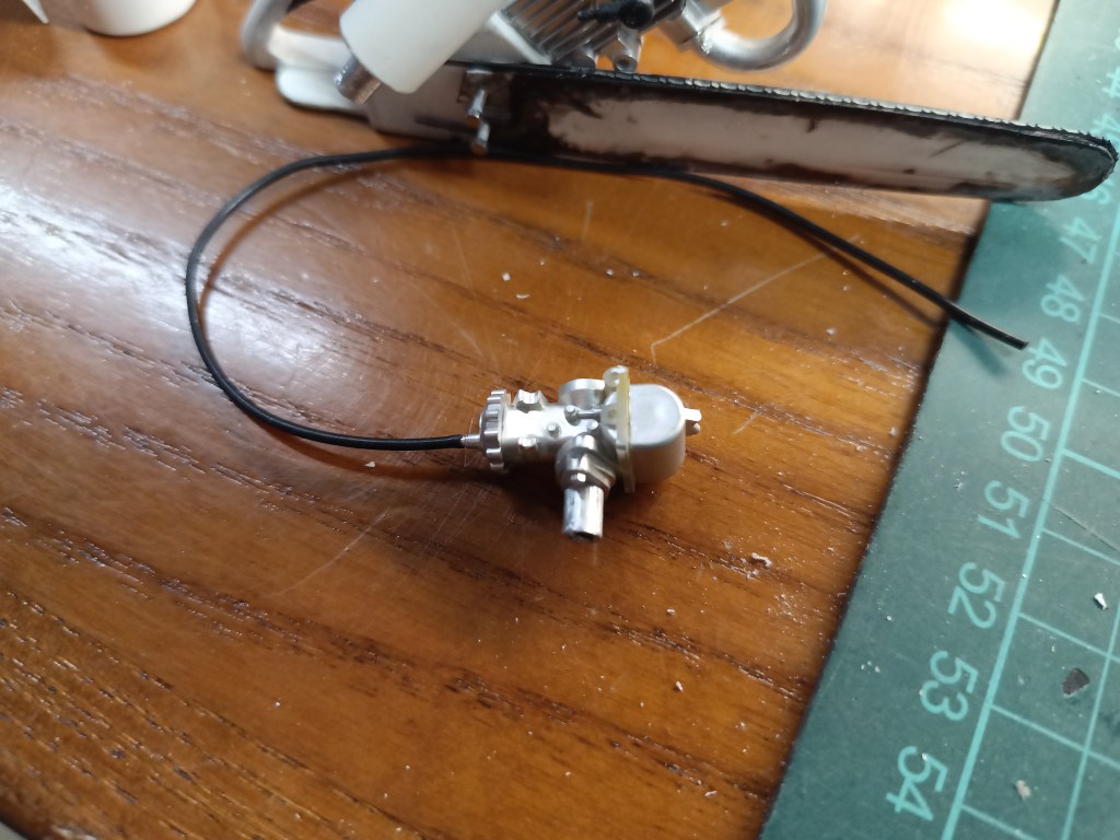
…und ein Zündkabel ins Motorgehäuse geführt.
Für den bisher nur am Zylinderflansch befestigten Auspuff gab es zusätzlich eine Schelle, angefertigt aus verzinktem Blech. Farbe hat der Schalldämpfer inzwischen auch bekommen.
Weiter ging es mit einem Haltebügel für die Maschine. Rechts auf dem Gehäuse befestigt und um die Kettensäge auf die andere Seite geführt. Durch das weiche Aluminiumrohr auch wunderbar zu biegen. Als Griffgummi habe ich hier einen Schrumpfschlauch über das Rohr gezogen.
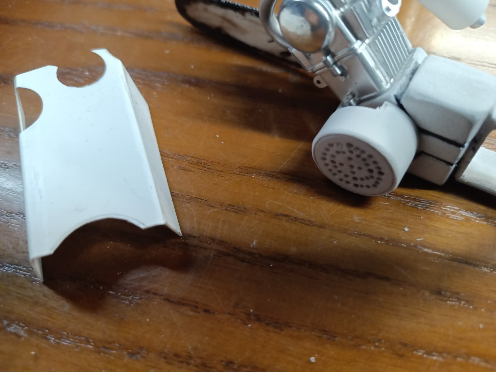
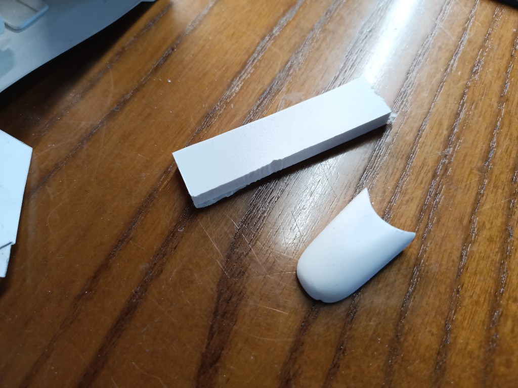
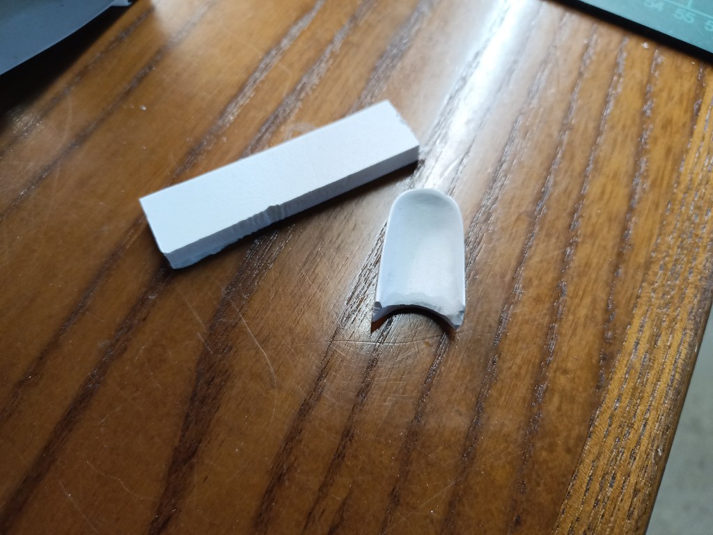
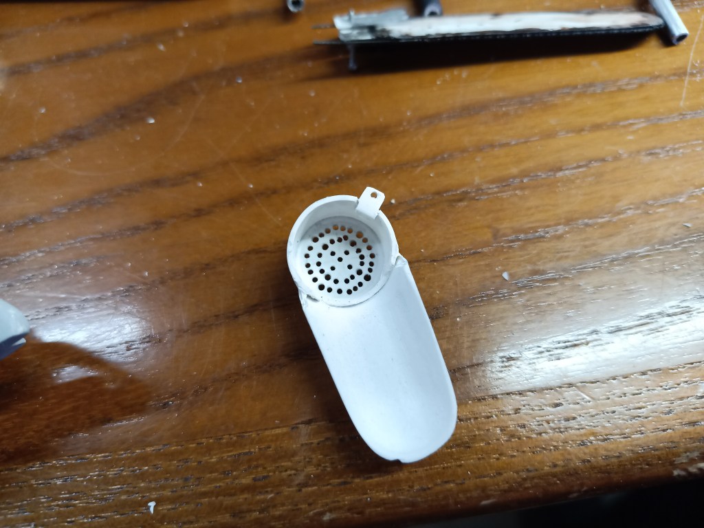
Das Kühlgebläse erhielt aus einem Stück Kunststoffrohr und einem gebohrten Deckel die notwendige Abdeckung. Nicht alle Bohrungen 1 mm sind mir exakt gelungen. Die äußeren Viertel wurden jeweils mit 1,3 mm gebohrt. Mit dem Handbohrer sind einige etwas verlaufen. Normal stört mich so eine Ungenauigkeit, passt aber zur Eigenbausäge und hat somit die interne QS-Kontrolle bestanden. Links im Bild der erste Entwurf meiner Kühlluftführung. Sie ist aber zu groß geraten und wird durch die nachfolgende Variante ersetzt.
Die entstand schließlich aus einem Forex-Block. Innen grob halbrund ausgefräst und außen Zug um Zug an die Zylinderstruktur angepasst. Bedeutet, mit Schmirgelleinen in Körnung 80 freihändig in Form geschliffen. Abschließend mit einem Cuttermesser noch auf der Innenseite die Zwangspunkte mit Kühlrippen und Ausformungen beseitigt. Zum Schluss noch eine kleine Lasche um die Abdeckung am Gehäuse festzuschrauben.
Mit Farbe und den ersten Beulen dann das nachfolgende Bild. Aus einem 3 mm Rohr und einer Inbusschraube wurde noch der Einfüllstutzen für die Kettenschmierung gebaut. Mit Farbe wird das Bild langsam vollständig.
Für den nächsten Schritt habe ich wieder etwas experimentiert. Der Luftfilter sollte wie ein konventioneller Papierfilter aussehen. Mit gefaltetem Papier zur Vergrößerung der Filterfläche.
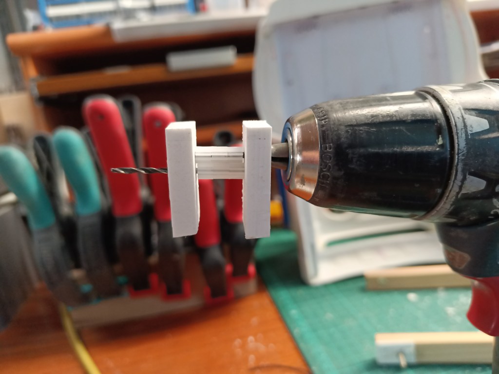
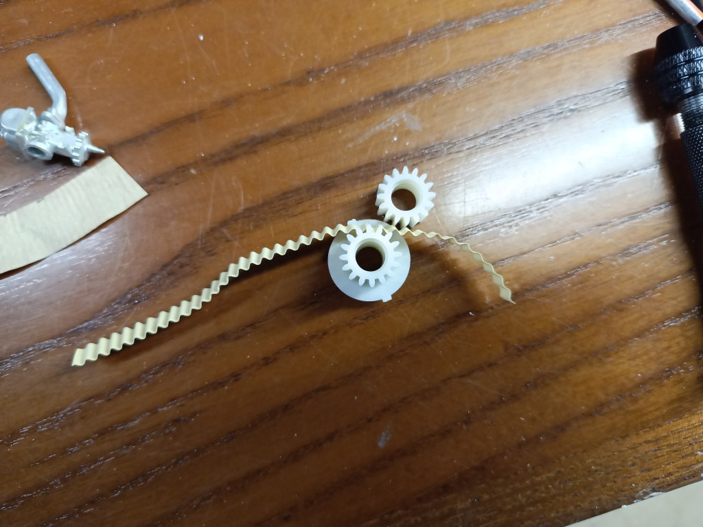
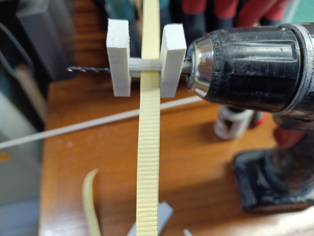
Auf ein Rohr 4 mm wurde zwei Scheiben als Abschluss ausgestanzt. Auf die Scheiben dann zwei Rohrstücke, etwa 1 mm dicker als die Scheiben. Um die schönste Filterstruktur zu schaffen, habe ich zwei verschiedenen Ritzel-Modulen und drei Sorten Papier verwendet. Sechs Ritzel Modul 0,5 wurden auf zwei Bohrer 2 mm gepresst und der berechnete Achsabstand von 4,5 mm in zwei Forex-Stücke gebohrt. Zusammengebaut entstand diese Konstruktion. Vom Akkuschrauber mit geringstmöglicher Geschwindigkeit angetrieben, wurde die verschiedenen Papiersorten im Durchlaufverfahren gefaltet.
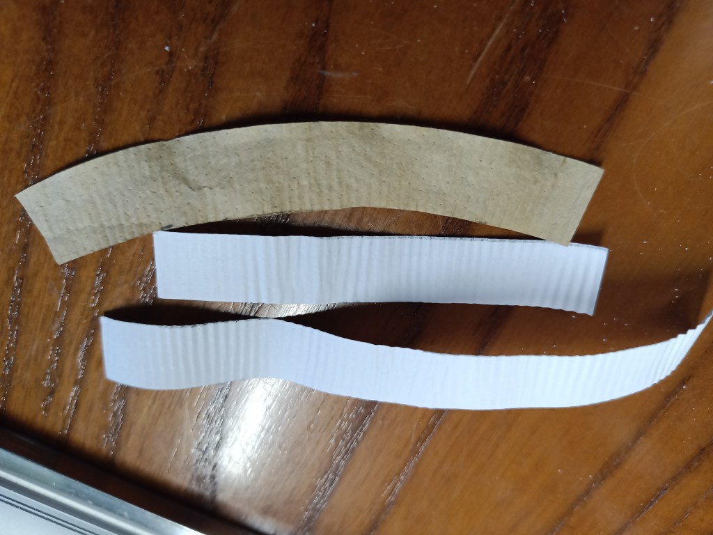
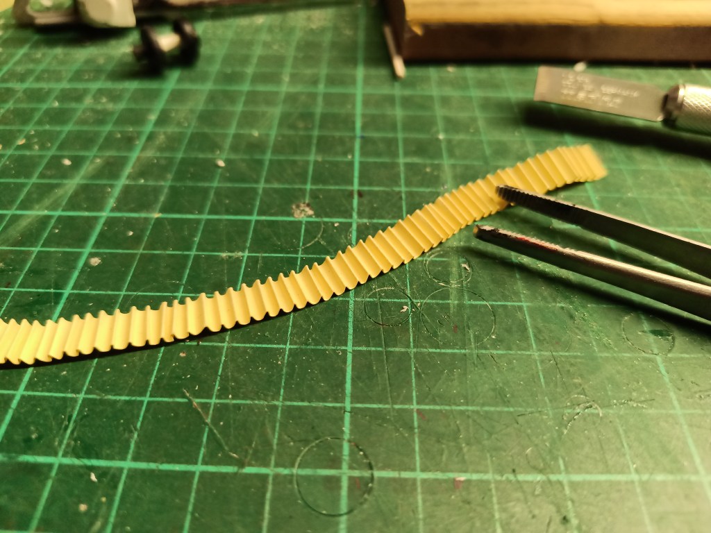
Links der Kaffeefilter war zu weich um bei Modul 0,5 eine Prägung zu erkennen. In der Mitte Bastelkarton und Modul 0,8 war nicht schlecht, aber zu grob. Eine akzeptable Lösung wäre die Kombination von Bastelkarton und Modul 0,5, rechts.
Dennoch habe ich mich für Modul 0,8 entschieden. Dazu wurde noch jede Falte einzeln mit der Pinzette geglättet, um die Faltendichte möglichst realistisch zu gestalten. Das so entstandene Bild kam meiner Vorstellung von Realität am nächsten.
Am Vergaser montiert dann das Ergebnis.
Nachdem noch aus Kleinteilen und Reststücken eine Abdeckung für den Ritzelantrieb und der Seilzugstarter gebaut waren, dass vorläufige Ergebnis.
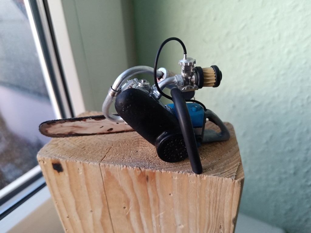
Es folgen noch kleine farbliche Optimierungen, die ich in einem der folgenden Beiträge vorstellen werde.
Wird schnellstmöglich fortgesetzt…
English Version
Making tools, part 10-How to build a do-it-yourself chainsaw.
Today’s post is about building a chainsaw. It will be an equipment detail of the workshop on the SuperScale 2026. There is already a high-quality and finely detailed model of the Stihl M500i in my collection.
But it would be far too good for the planned jungle house on the SuperScale 2026. My competition entry is a jungle hut with a corrugated iron roof. Part of the site is to have a stone wall, to which a small covered workshop is to be attached. A tight construction program for 2025 is therefore already in place. Now to the construction of the saw. It has no real-life model and is powered by a 4-stroke engine. The crankcase is home-made, as is everything to do with the jungle saw. Creativity will once again be in the foreground. So here we go. Two blocks were cut from forex scraps and glued together. In the foreground is the cylinder of a Honda Monkey, which was used for a different purpose.
The first contours were milled and carved from the block. However, there is still too much material on the monster saw.
A little more filigree would be desirable. So further slimming down. The contours of the fuel and chain oil tanks were set off and outlined in color to assess the proportions.
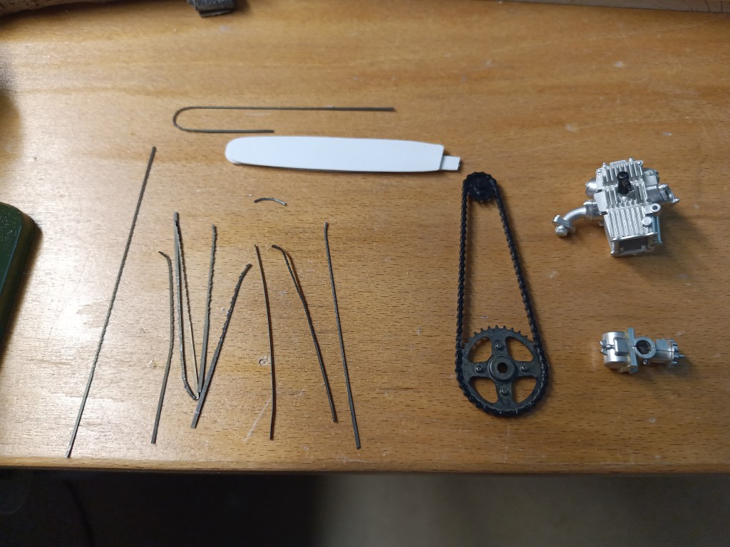
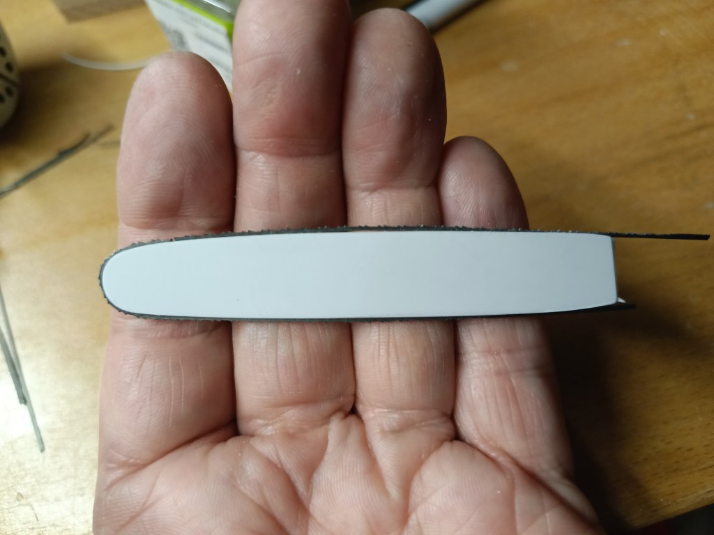
The sword is three-layered with a slightly smaller middle section. So small that a fretsaw blade can still be visible in it. They have been cold bent in many tests. Saw blades are usually hardened and therefore anything but bend-friendly. My stock was therefore somewhat depleted. The picture above shows a successful attempt.
The missing lower part was cut from a scrap piece. It won’t be noticeable later as long as no magnifying glass comes into play. Glued with superglue.
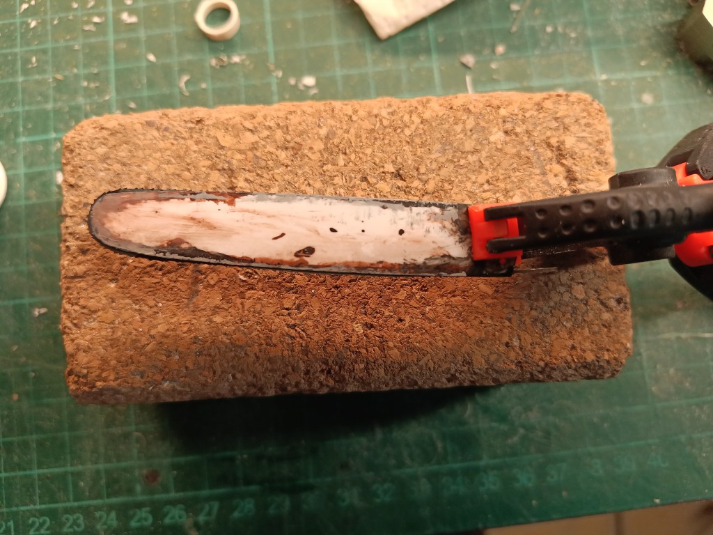
The sword was also immediately given its first signs of use. These will be touched up a little after drying.
Before we continue with the covers for the saw chain and the cooling fan, the preliminary state of construction. A 4-stroke engine like this is somewhat larger and still fits in well with the filigree Stihl original. Both in 1:10 scale.
Some cooling fins were milled into the crankcase…
…and the cooling fan was painted red.
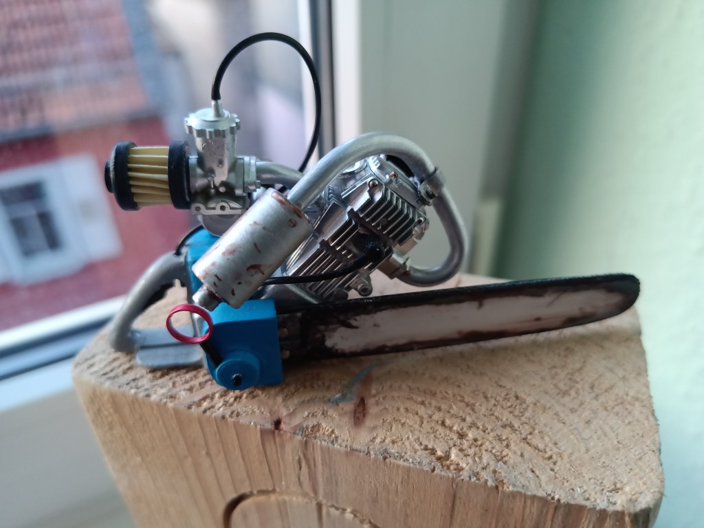
A narrow bend was formed from 4 mm soft aluminum tubing as an exhaust system. The silencer was made from two pieces of pipe pushed into each other. Two caps were punched out and drilled with 4 mm holes. Everything was pushed over the pipe and the exhaust was finished.
The throttle cable was connected to the carburetor…
…and an ignition cable was fed into the engine housing.
For the exhaust, which was previously only attached to the cylinder flange, there was an additional clamp made from galvanized sheet metal. The silencer has also been painted in the meantime.
We continued with a mounting bracket for the machine. Attached to the right side of the housing and guided around the chainsaw to the other side. The soft aluminum tube makes it easy to bend. I pulled a shrink tube over the tube as a rubber grip.
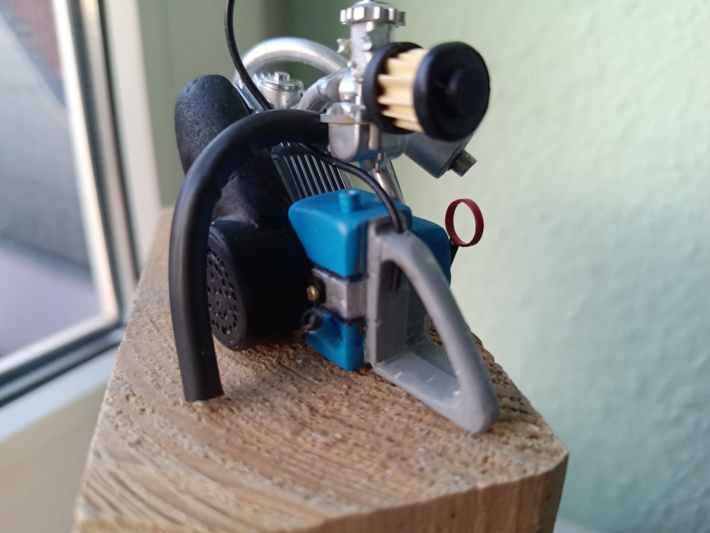
The cooling fan was given the necessary cover from a piece of plastic tube and a drilled cover. I didn’t manage to drill all the 1 mm holes exactly. The outer quarters were each drilled to 1.3 mm. With the hand drill, some of them ran a little. Normally, this kind of inaccuracy bothers me, but it suits the self-made saw and has therefore passed the internal Quality check. The picture on the left shows the first draft of my cooling air duct. However, it turned out to be too large and will be replaced by the following version.
This was finally made from a forex block. Roughly milled half-round on the inside and adapted to the cylinder structure step by step on the outside. In other words, sanded into shape freehand with 80 grit emery cloth. Finally, the constraint points with cooling fins and moldings were removed on the inside with a cutter knife. Finally, a small tab was added to screw the cover to the housing.
With paint and the first dents then the following picture. The filler neck for the chain lubrication was made from a 3 mm tube and an Allen screw. With paint, the picture slowly becomes complete.
For the next step, I experimented a little again. The air filter should look like a conventional paper filter. With folded paper to increase the filter area.
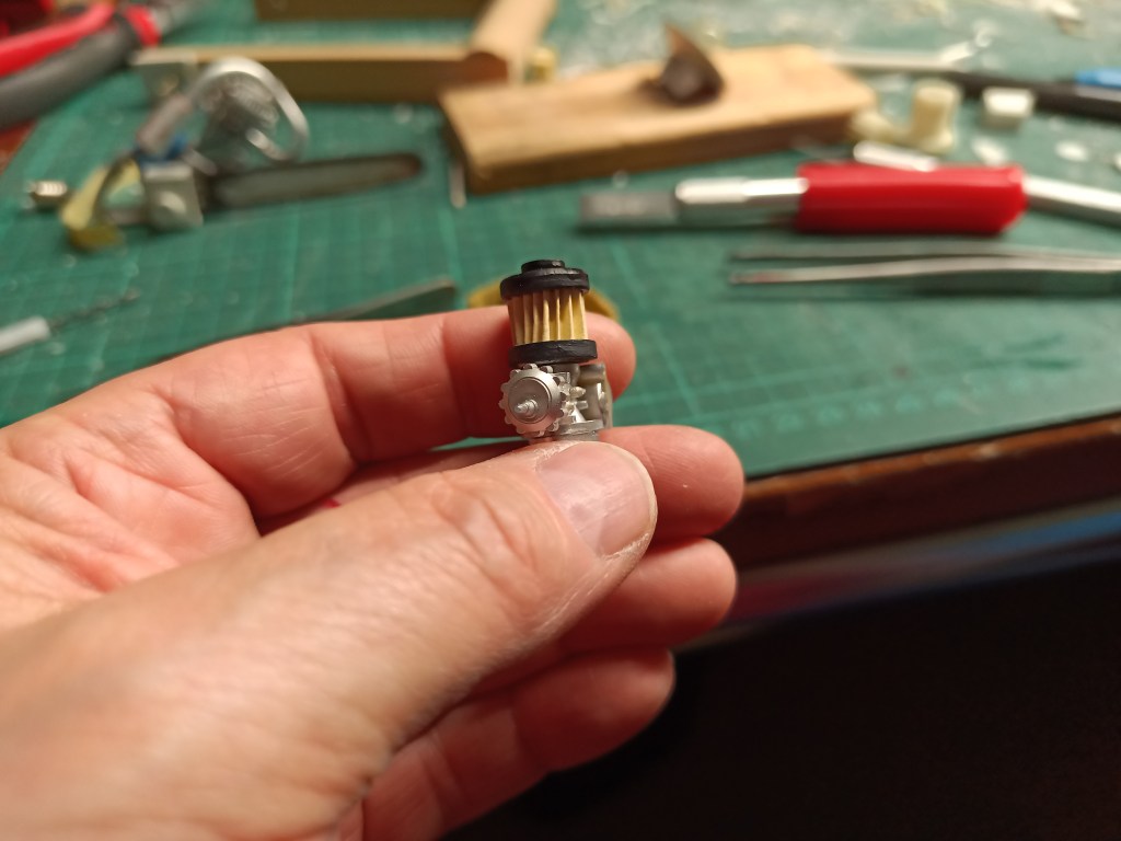
Two discs were punched out on a 4 mm tube to form the end. Then two pieces of tube, about 1 mm thicker than the disks, were placed on the disks. To create the most beautiful filter structure, I used two different pinion modules and three types of paper. Six pinions module 0.5 were pressed onto two 2 mm drills and the calculated center distance of 4.5 mm was drilled into two Forex pieces. This construction was assembled. Driven by the cordless screwdriver at the lowest possible speed, the different types of paper were folded in a continuous process.
On the left, the coffee filter was too soft to recognize an embossing at module 0.5. In the middle, craft cardboard and module 0.8 was not bad, but too coarse. An acceptable solution would be the combination of craft cardboard and module 0.5 on the right.
Nevertheless, I opted for module 0.8. Each fold was smoothed out individually with tweezers to make the fold density as realistic as possible. The resulting picture came closest to my idea of reality.
Mounted on the carburetor, the result.
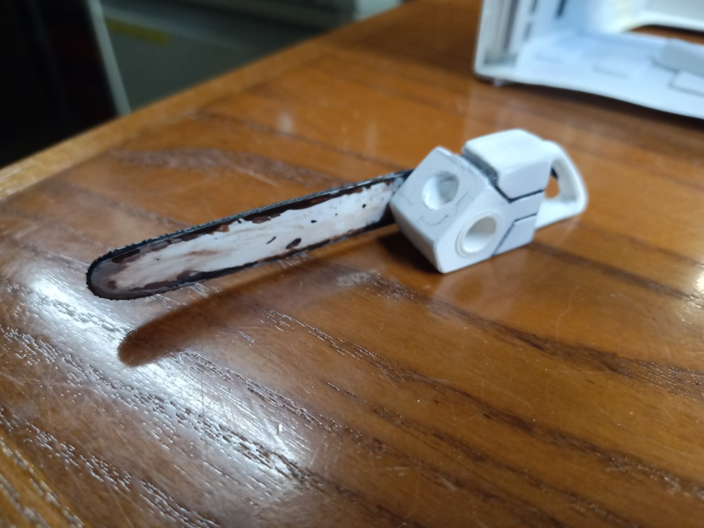
After building a cover for the pinion drive and the cable starter from small parts and remnants, the preliminary result.
There are still small color optimizations to come, which I will present in one of the following posts.
Will be continued as soon as possible…
Translation, with the kind support of deepl.com
