English Version
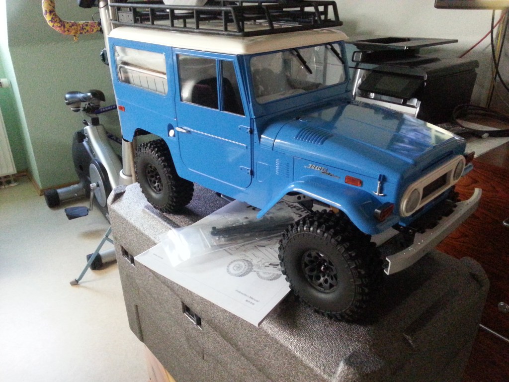
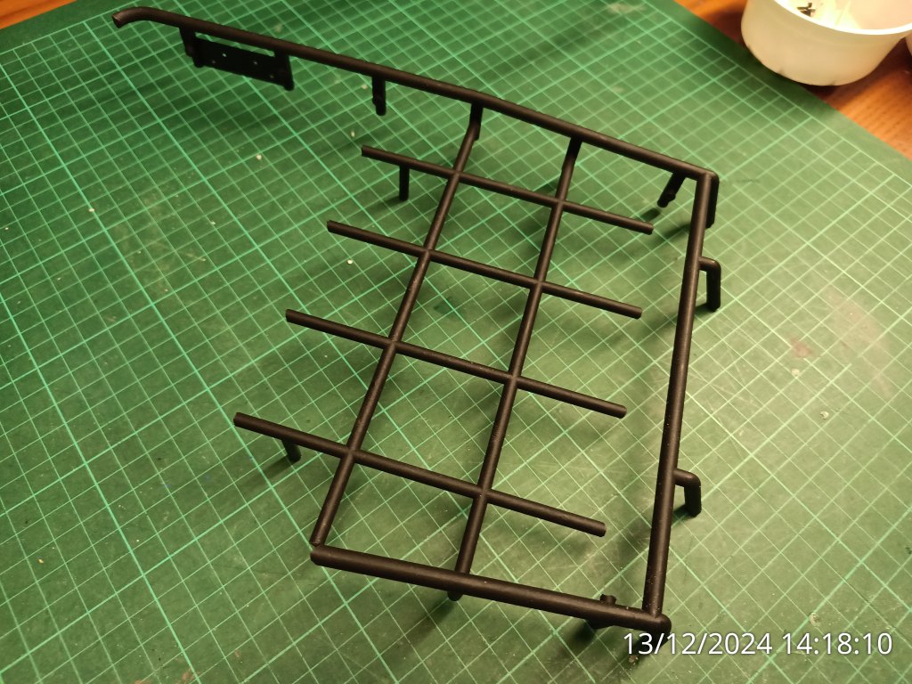
Der Rat Comanche ist und wird kein Kampffahrzeug. In einer für uns noch fiktiven Zukunft wird aber Robustheit der Garant für den Fortbestand sein. Das will ich auch am Comanche darstellen. Dazu erhält er einen Überrollkäfig im Fahrerhaus. Für gewöhnlich würde ich im Innenraum leichte Kunststoffrohre verbauen. Außen hingegen eher Rohrmaterial aus Metall verwenden. In diesem Fall habe ich eine andere Variante gewählt. Nicht etwa aus Bequemlichkeit oder Unvermögen. Vom Bau meines letzten Modells, dem FMS Toyota FJ40, lag hier schon einige Monate ein völlig überdimensionierter Dachgepäckträger herum. Er ist aus zwei Ebenen hergestellt und miteinander verschraubt.
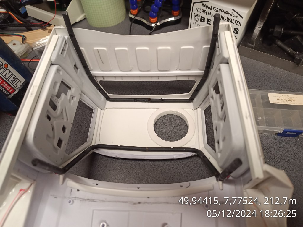
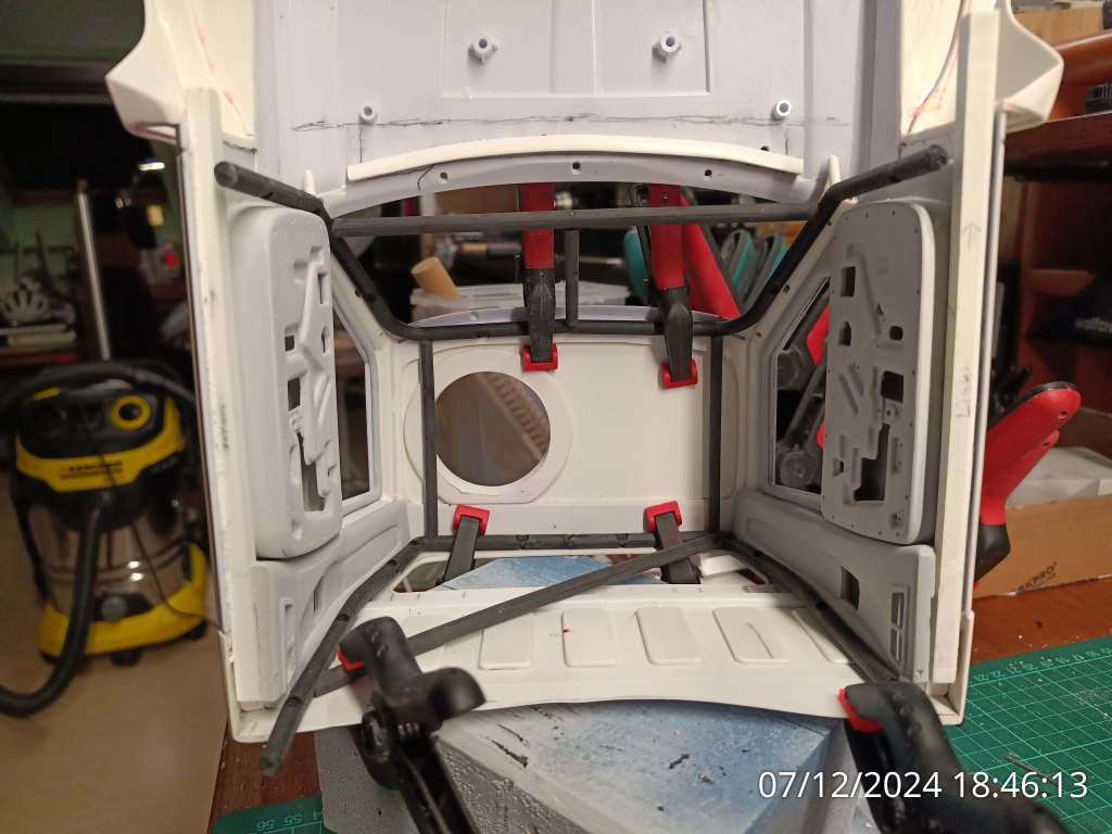
Für den hinteren Bügel wurde ein Teil der angespritzten Streben entfernt und beigeschliffen. Die Form des Bügels war nach dem Dach des Toyota entsprechend geformt. Es besteht aus widerstandsfähigem Kunststoff, der sich auch warm nur schwer umformen lässt. Schwer umformen heißt aber hier nicht, dass es überhaupt nicht geht. Zunächst also das geformte Rohrelement einmal in der Mitte durchtrennen. Mit 220 °C habe ich den Kunststoff aufgeheizt, bis er sich langsam bewegen lässt und an die Innenraumkontur angepasst werden konnte. Zum Schluss noch die beiden Enden in der Dachmitte markieren und kürzen. Erste Verbindungsversuche mit 1 mm Kunststoffstiften und Sekundenkleber waren nicht geeignet. Der von mir gewählte Kleber hält nicht und die Kunststoffverbindung bricht sofort bei geringster Biegelast.
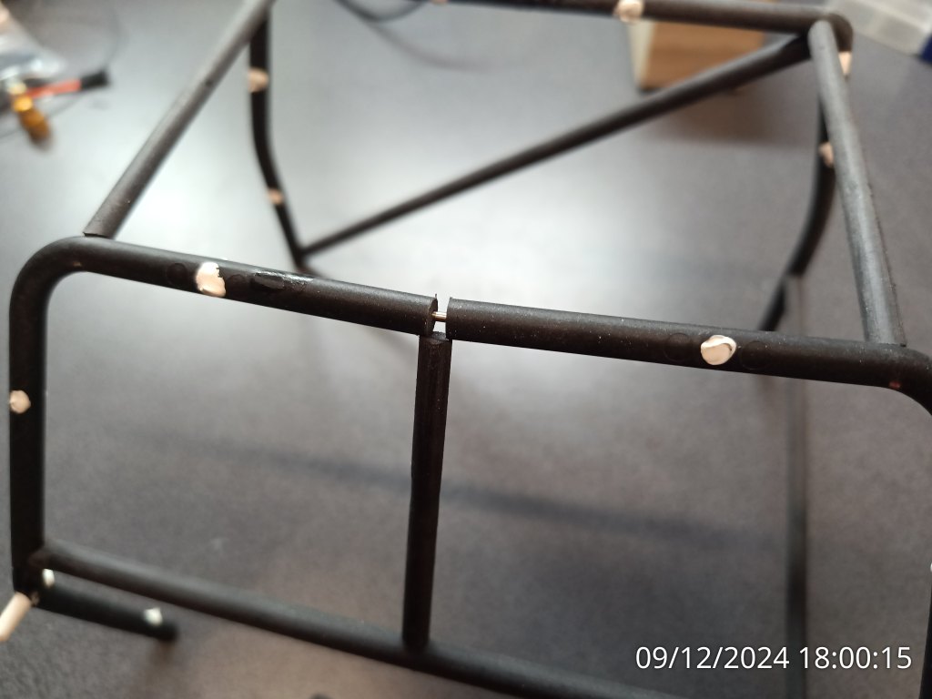
Daher habe ich die zentrierten Bohrungen auf 1,4 mm aufgebohrt und anstelle von Kunststoff, 1,5 mm Silberstahl verwendet. Das sieht in einem fortgeschrittenen Baustadium so aus. Die links, sichtbare, obere Verbindungsstelle wird auch weiter unten noch einmal ein Thema werden.
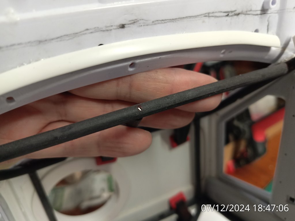
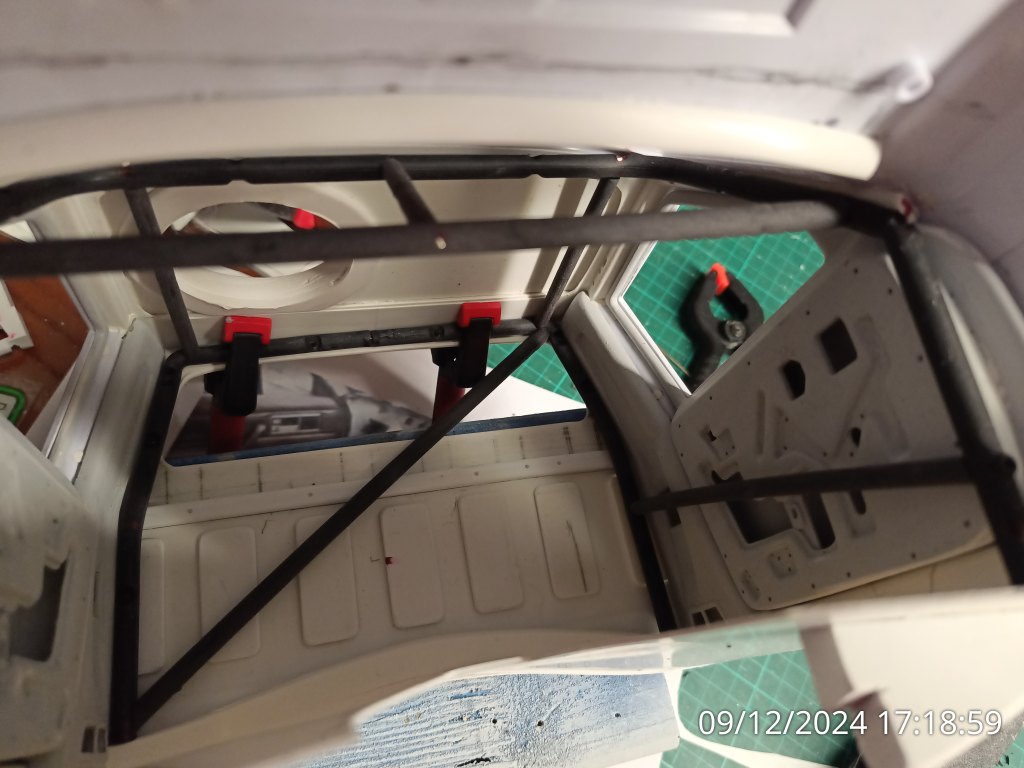
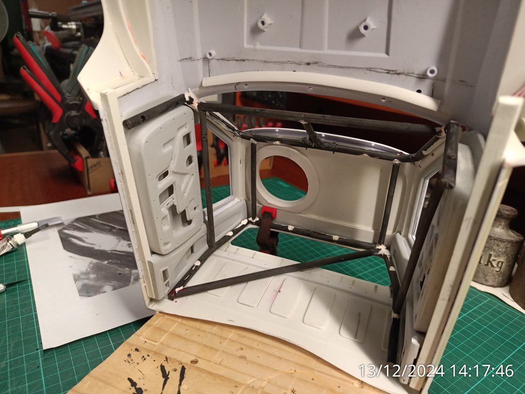
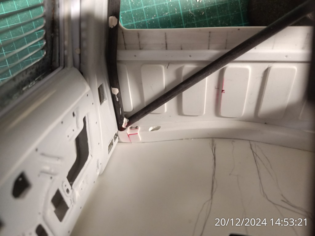
Zusätzliche Verstrebungen unter dem Dach, in der Frontscheibe und einer Diagonale auf der Rückseite des Fahrerhauses ergänzen das Gebilde zu einem Käfig. Wie schon beschrieben, alles aus den Resten des Dachgepäckträgers. Das ist auf den Fotos auch an den Bohrungen und Aussparungen teilweise noch erkennbar. An den Anbindungsstellen wurden alle Rohre mit der Rundfeile auf den Winkel und die jeweiligen Konturen angepasst.
Als finale Schutzmaßnahme erhielt der Fahrer einen Flankenschutzbügel.
Es gibt zwar keinen Beifahrerplatz, aber auch hier gab es der Vollständigkeit halber eine Schutzstrebe. Die wurde aber auf der Unterkante des Fensterrahmens montiert.
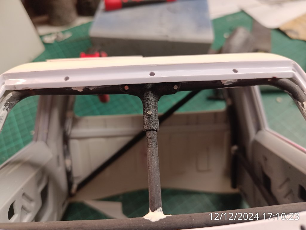
Die in der Frontscheibe verbaute Stützstrebe benötigte aber noch eine zusätzliche Befestigung. Zwei Gründe waren dafür ausschlaggebend. Zum einen wollte ich ursprüngliche zwei senkrechte Stützen verbauen, um damit den mittig angeordneten Verbindungsstift nicht zu treffen. Gut gedacht, aber leider brach beim Ausfeilen der Rundung einer der Stäbe ab. Ich war ehrlich gesagt zu faul, einen Neuen anzufertigen. Das half aber trotzdem nichts, so stießen jetzt zwei Stifte im T aufeinander. Einer horizontal und ein weiterer senkrecht von unten. Der so entstandene Zwangspunkt ist auf dem weiter oben zu sehenden, linken Galerie-Foto erkennbar.
Aus einer leicht zu formenden Kunststoffplatte, entstand durch Erwärmen dieses Bauteil.

Das war mir dann aber doch zu formatfüllend und wurde einer finalen Abmagerungskur unterzogen. Das deutlich ansehnlichere Ergebnis wie folgt…
Viel ist vom ursprünglichen Dachgepäckträger nicht übriggeblieben und wurde so einer neuen Aufgabe zugeführt. Der untere Tragrahmen ist fast vollständig in den beiden Bügeln aufgegangen und der Rest hat für die vielen Streben hergehalten.
Zum Abschluss für heute, eine letzte, kleine Baustelle im Jahr 2024. Die Bodenbefestigung für den hinteren Käfig. Eine Bohrung in einem 3 mm Kunststoffrest nimmt den Bügel auf und wird von einem gebogenen und angepassten Winkel mit 3 Schrauben M 1,4 auf dem Bodenblech verschraubt.

🎄🎄An dieser Stelle möchte ich mich gerne bei allen Interessierten bedanken. Auch für die Kommentare und vielfältigen Reaktionen. Ihnen allen wünsche ich ein wunderbares und beschauliches Weihnachtsfest im Kreis ihrer Liebsten. Dazu Glück und Gesundheit und einen hoffentlich, friedvollen Übergang ins das Neue Jahr 2025. ❤️
Wird schnellstmöglich fortgesetzt…
English Version
Merry Christmas 2024 and my way to build a model roll cage
The Rat Comanche is not and will not be a combat vehicle. However, in a future that is still fictitious for us, robustness will be the guarantee for its continued existence. I also want to demonstrate this with the Comanche. To this end, it will have a roll cage in the cab. I would normally use lightweight plastic tubing in the interior. On the outside, however, I tend to use metal tubing. In this case, I chose a different variant. Not out of convenience or inability. From the construction of my last model, the FMS Toyota FJ40, a completely oversized roof rack had been lying around here for several months. It is made from two levels and bolted together.
For the rear bracket, some of the molded struts were removed and sanded down. The shape of the bracket was modeled after the roof of the Toyota. It is made of resistant plastic, which is difficult to reshape even when warm. However, difficult to form does not mean that it cannot be formed at all. First of all, I cut the molded tubular element in the middle. I heated the plastic to 220 °C until it could be moved slowly and adapted to the interior contour. Finally, mark and shorten the two ends in the middle of the roof. Initial attempts at joining with 1 mm plastic pins and superglue were not suitable. The adhesive I chose did not hold and the plastic joint broke immediately under the slightest bending load.
I therefore drilled out the centered holes to 1.4 mm and used 1.5 mm silver steel instead of plastic. This is what it looks like at an advanced stage of construction. The upper joint visible on the left will also be an issue further down.
Additional struts under the roof, in the windshield and a diagonal on the back of the cab complete the structure to form a cage. As already described, everything is made from the remains of the roof rack. This is still partially visible in the photos from the drill holes and recesses. At the connection points, all the tubes were adjusted to the angle and the respective contours using a round file.
As a final protective measure, the driver was fitted with a flank guard.
Although there is no passenger seat, there was also a protective strut here for the sake of completeness. However, this was mounted on the lower edge of the window frame.
However, the support strut installed in the windshield required an additional attachment. There were two reasons for this. Firstly, I originally wanted to install two vertical supports so as not to hit the central connecting pin. Good thinking, but unfortunately one of the rods broke off when I was filing out the curve. To be honest, I was too lazy to make a new one. But it still didn’t help, so now two pins in the T met. One horizontally and another vertically from below. The resulting constraint point can be seen in the Gallery photo on the left.
This component was then made from a plastic plate that was easy to shape by heating.
However, this was too full-size for me and underwent a final slimming treatment. The much more attractive result is as follows…
Not much was left of the original roof rack, so it was given a new purpose. The lower support frame has been almost completely absorbed into the two brackets and the rest has been used for the many struts.
Finally for today, one last small construction site in 2024: the floor mounting for the rear cage. A hole in a 3 mm piece of plastic holds the bracket and is screwed to the floor panel with 3 M 1.4 screws using a bent and adapted bracket.
🎄🎄I would like to take this opportunity to thank all those interested. Also for the comments and diverse reactions. I wish you all a wonderful and peaceful Christmas with your loved ones. In addition, happiness and health and hopefully a peaceful transition into the New Year 2025. ❤️
Will be continued as soon as possible…
Translation, with the kind support of deepl.com
