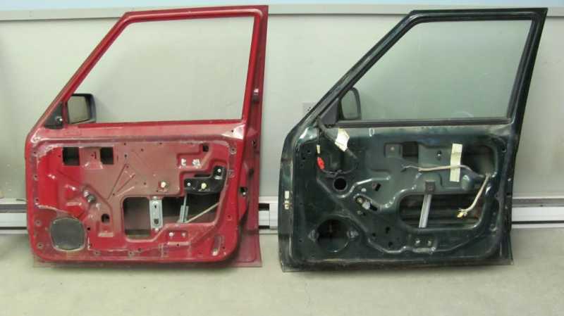
Quellen: Internet Fotosuche
English Version
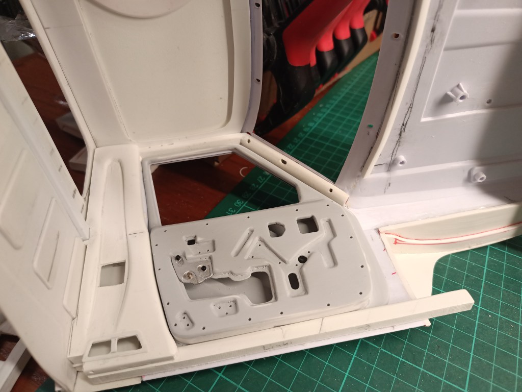
Im Zuge der äußeren Hülle des Fahrerhauses, sind schon erste Teile der später sichtbaren Blechstruktur entstanden. Nun also die Fortsetzung der bereits begonnen Arbeiten. Teile davon waren auch schon im letzten Beitrag zu erkennen.
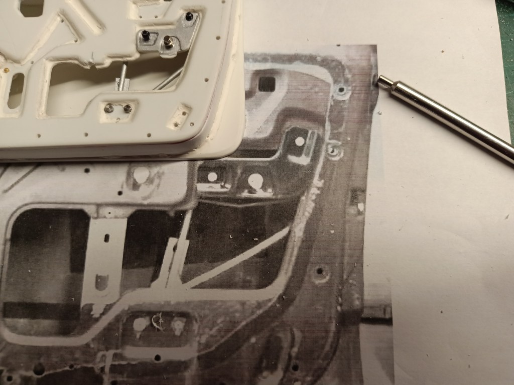
Nach der nachfolgenden Vorlage wurde eine Kopiervorlage erstellt. Maßstäblich im Drucker verkleinert und wieder mit Blaupapier auf Kunststoffplatten übertragen.
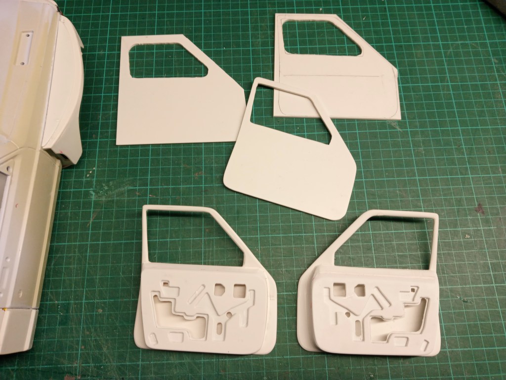
Mit der Laubsäge und Cuttermesser hatte ich die Konturen herausgearbeitet. Um wieder eine dreidimensionale Wirkung zu bekommen, noch eine 0,5 mm Kunststoffplatte auf die Rückseite geklebt. Aus einer 6 mm starken Forex-Platte entstand noch die Umrandung der Türfüllung. Miteinander verklebt und bearbeitet das nachfolgende Ergebnis. Die Form der Tür wurde so geformt, dass sie mit der Kontur der Seitenwand übereinstimmt. Dazu wurde der Kunststoff eingeritzt und warm verformt.

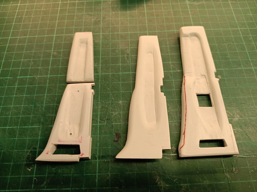
Für das Blechprofil hinter der B-Säule musste ich etwas Neues probieren. Die mittlere Ausführung wurde schon für den Innenraum des Comanche Truggys gebaut. War mir aber noch nicht perfekt genug. Zudem sind die Maße nicht exakt zum Rat Comanche passend. Jedes Modell ist praktisch ein Einzelstück, somit alles nur ähnlich. Auf der linken Seite also zunächst ein Versuch aus zwei Teilen. Rechts dann die neue Version für den Rat Comanche. Noch nicht vollständig bearbeitet.
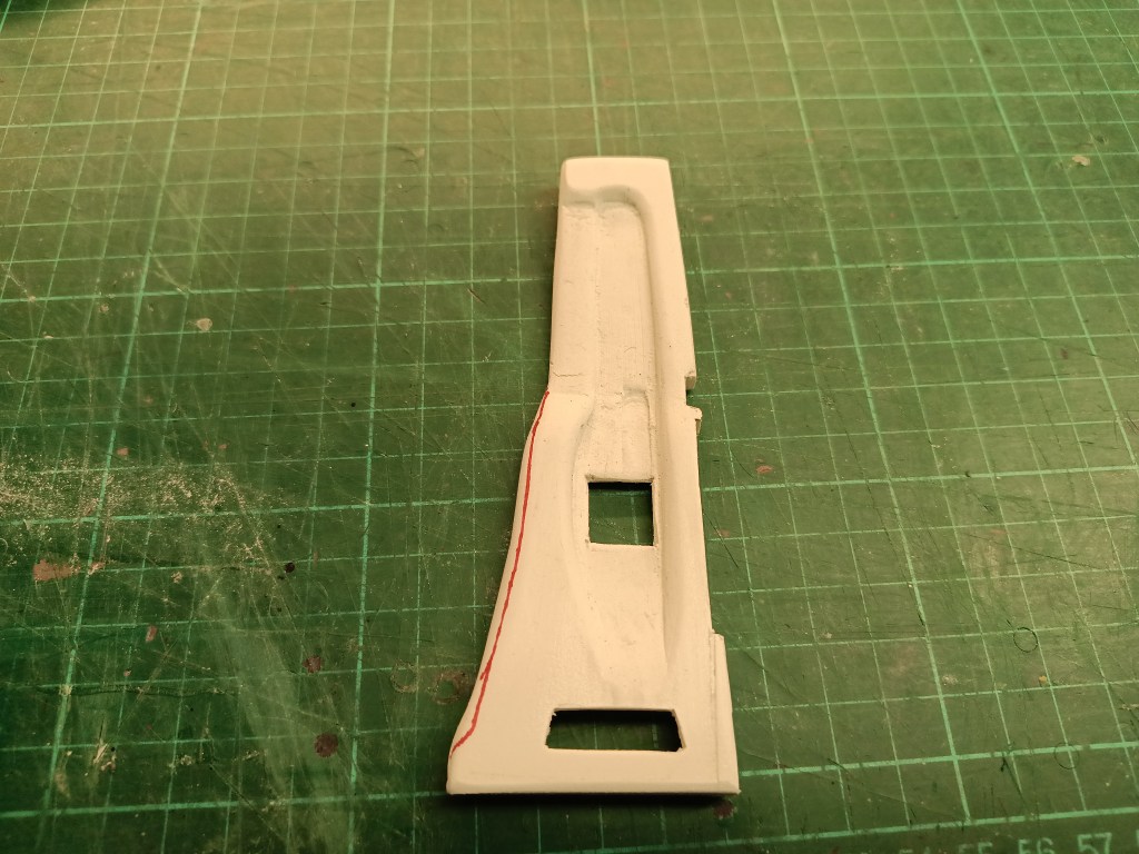
Daraus entstanden schließlich zwei komplette Seitenteile. Aufwändig auf der Vorder- und Rückseite bearbeitet. Zum Schluss auch noch warm gebogen, um zur Fahrerhauskontur zu passen. Wie beim Original, am unteren Rand eine aufgesetzte Struktur.
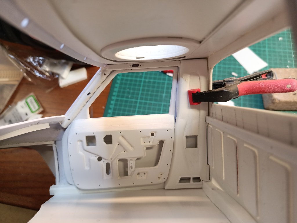
Im Fahrerhaus sah das zwischenzeitlich so aus…
Auch an der Dachunterseite und ebenso der A-Säule wurde intensiv gearbeitet. Eine aus 0,5 mm PS-Kunststoff ausgeschnittenes Profil wurde unter das Dach geklebt. Durch den erhabenen Rand unter der Dachhaut entsteht so eine Schattenfuge, wie auch beim Original. Aus Resten von 6 mm Forex habe ich die A-Säulenprofile geschliffen. Auf der Rückseite wieder mit Ausfräsungen, damit ein Hohlraum hinter den Durchdringungen erkennbar ist.
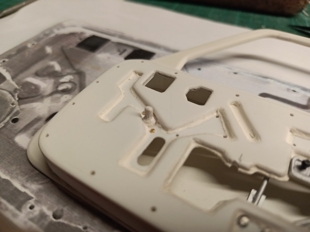
Die Türstruktur wurde final mit Vallejo Plastic Putty bearbeitet. Insbesondere die bisher harten Kanten der Sicken wurden so aufgebaut und geschliffen. Anschließend mit Spritzspachtel lackiert und feingeschliffen. Weiterhin baute ich noch zwei Halterungen für den Fenstermechanismus. Nur aus optischen Gründen, um die Türen noch realistischer aussehen zu lassen. Diese scheinbar recht einfachen Teile wurden noch zusätzlich ausgefräst. So sollte der Eindruck einer geprägten Blechplatte dargestellt werden, Nicht ganz einfach auf einer Fläche von 2×1 cm.
Für den Bereich zwischen A- und B-Säule habe ich zwei Längsprofile hergestellt, die die beiden Säulenprofile unter dem Dach verbinden. So sieht das Ensemble auf der Fahrerseite jetzt aus. Um alles unterzubringen, musste dazu noch Nacharbeiten an den Türprofilen vorgenommen werden. Geklebt wird bei mir erst, wenn alle Teile an ihrem Platz sind und vor allen Dingen auch zueinander passen. So dann das Ergebnis.
Auf der Beifahrerseite wurde an den sichtbaren Teilen des Fensterhebers weitergearbeitet. Ganz rechts zwei Gestänge, am Türprofil mit zwei Schrauben befestigt.
Auf der linken Seite die gezahnte Kurbelaufnahme für den Fensterheber.
Die Entstehung, wieder einmal durch Improvisation. Ein 5 mm Stab ins Bohrfutter der Bohrmaschine eingespannt und mit der Flachklinge herausgedrechselt. Feinarbeiten und Rundungen abschließend mit Schmirgelpapier. Zum Abschluss habe ich mit einer feinen Spitzzange und Feingefühl die Verzahnung eingeprägt.
So oft man auch prüft und kontrolliert, irgendein Detail entgeht einem immer. In der unteren Aussparung gibt es noch mittig eine Metalllasche. Als ich die eingebaut hatte, sah es seltsam aus. Beim genauen Studium des Originals entdeckte ich noch einen Fehler….

Also musste dieser Fehler noch ausgebügelt werden. Nach erfolgter minimaler Korrektur und einem weiteren Auftrag von Spritzspachtel, dann ein leicht verändertes Bild.
Nicht das alles perfekt nach dem Original gebaut ist. Die Bilder zeigen das ausdrücklich. Die verschiedenen Ebenen der Blechstruktur habe ich nur vorbildähnlich dargestellt. Da wäre noch einiges mehr herauszuarbeiten gewesen. Aber es hat schon so etwas außergewöhnliches und reicht mir auch für das erste Mal aus. Nie zuvor habe ich so etwas gebaut, ohne Drucker und frei Hand. Nur nach sehr kleinen Fotos in geringster Auflösung. Aber glücklicherweise habe ich wenigstens diese Vorlagen im Internet gefunden.
Vor weiteren Einbauten musste noch ein zusätzliches Teil gebaut werden. Dazu habe ich auf ein nicht mehr benötigtes Teil, den Dachgepäckträgers vom Toyota FJ40, zurückgegriffen. Etwas umgearbeitet und an neuer Stelle wieder zum Leben erweckt.
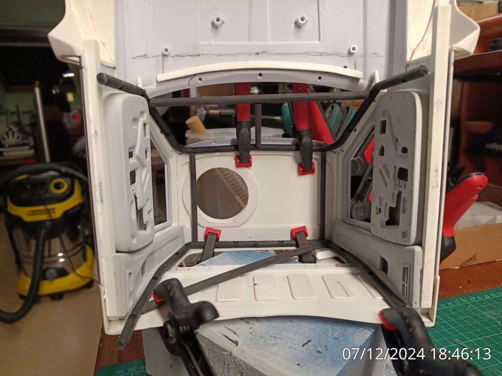
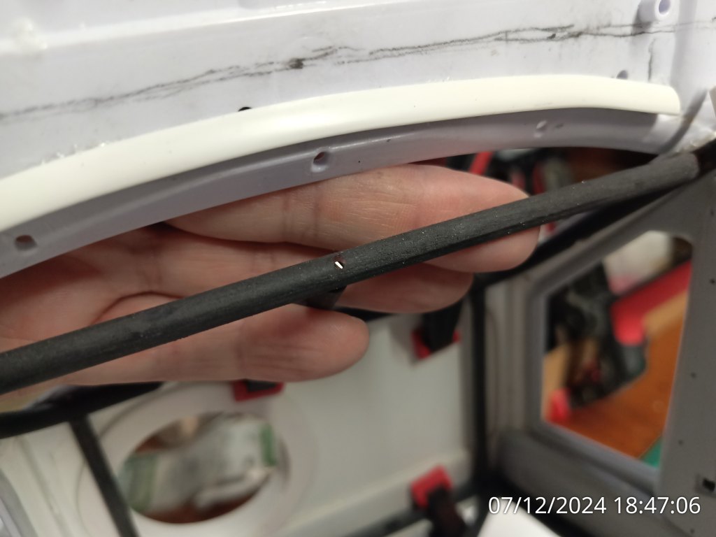
Die Stäbe sind auf Winkel und Form angepasst, durchbohrt und mit 1,5 mm Silberstahl-Stiften fixiert. Nach Lackierung werden die Punkte wohl nicht mehr sichtbar sein. Bohrungen des mehrteiligen Bauteils müssen noch geschlossen und gespachtelt werden.
Dieser Zwischenschritt war noch nötig, bevor es am Armaturenbrett und der Bodengruppe weitergehen kann. Der Bau des freitragenden Armaturenträgers orientiert sich dann an den vorhandenen Gegebenheiten. Es gibt ja kein konventionelles Armaturenbrett, sondern eine Improvisation aus notwendigen Instrumenten und Schaltern.
Wird schnellstmöglich fortgesetzt…
English Version
Überschrift
Sources: Internet Image Search
In the course of the outer shell of the cab, the first parts of the later visible sheet metal structure have already been created. Now the continuation of the work already started. Parts of it were already visible in the last article.
A copy template was created using the following template. Scaled down in the printer and again transferred to plastic sheets using blue paper.
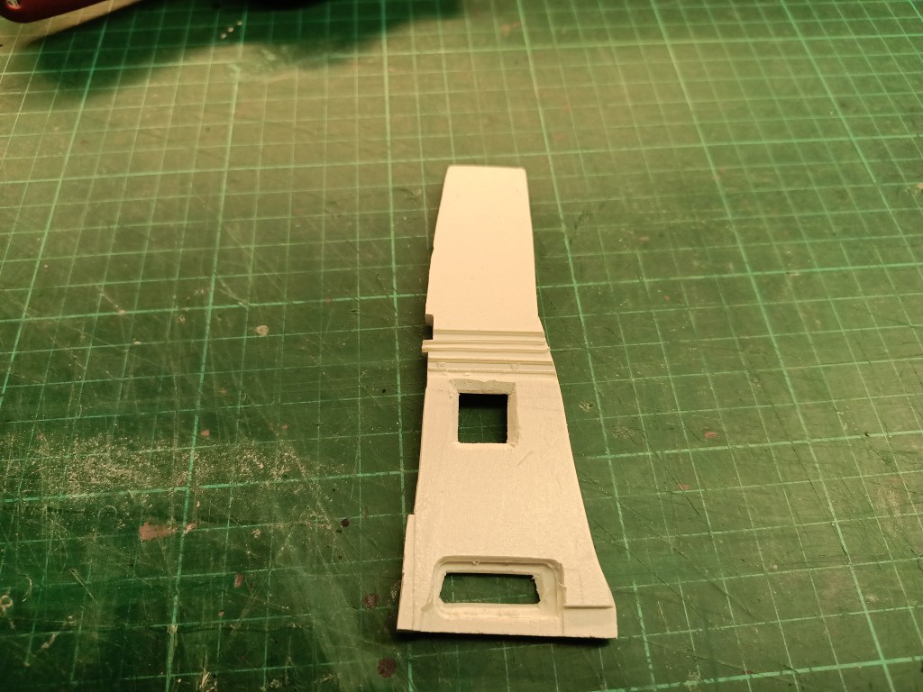
I worked out the contours with a fretsaw and cutter knife. To achieve a three-dimensional effect again, I glued a 0.5 mm plastic sheet to the back. The border of the door panel was created from a 6 mm thick forex panel. The following result was glued together and processed. The shape of the door was shaped to match the contour of the side panel. To do this, the plastic was scored and thermoformed.
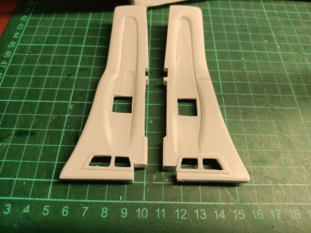
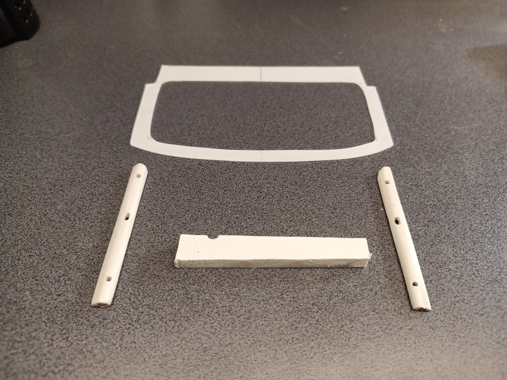
I had to try something new for the sheet metal profile behind the B-pillar. The middle version had already been built for the interior of the Comanche Truggy. But it wasn’t perfect enough for me. In addition, the dimensions don’t exactly match the Rat Comanche. Each model is practically unique, so everything is similar. So on the left is an initial attempt using two parts. On the right, the new version for the Rat Comanche. Not yet completely finished.
This ultimately resulted in two complete side panels. Elaborately machined on the front and rear. Finally, they were also hot-bent to fit the cab contour. As with the original, an attached structure on the lower edge.
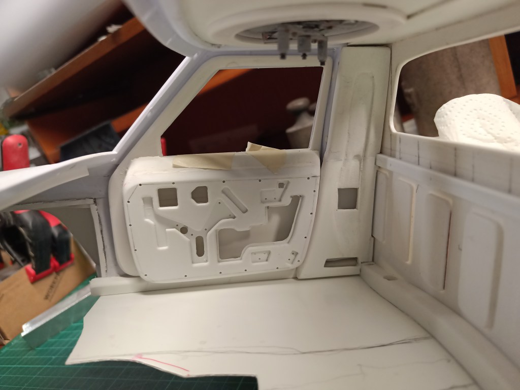
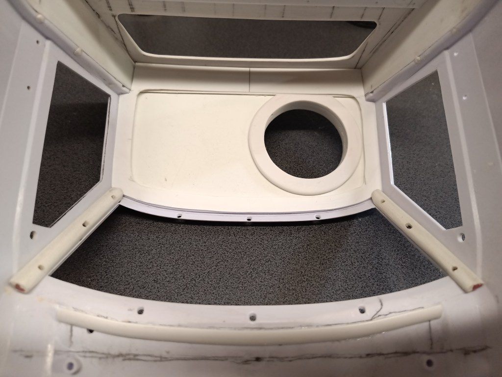
In the cab it looked like this in the meantime…
Intensive work was also carried out on the underside of the roof and the A-pillar. A profile cut out of 0.5 mm PS plastic was glued under the roof. The raised edge under the roof skin creates a shadow gap, just like the original. I sanded the A-pillar profiles from scraps of 6 mm Forex. Again with cut-outs on the back so that a cavity behind the penetrations is visible.
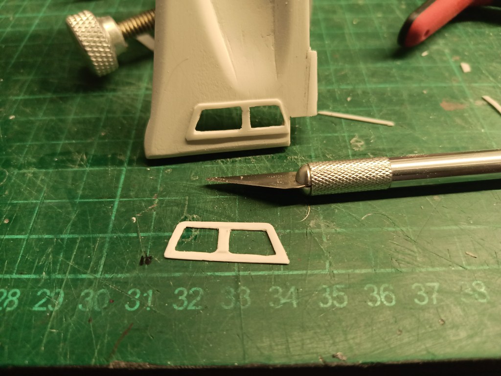
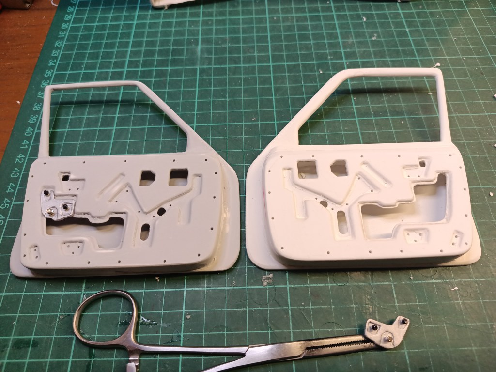
The door structure was finished with Vallejo Plastic Putty. In particular, the previously hard edges of the beading were built up and sanded. Then painted with spray putty and sanded. I also built two brackets for the window mechanism. Just for visual reasons, to make the doors look even more realistic. These seemingly simple parts were also milled out. The aim was to create the impression of an embossed sheet metal plate, which is not easy to do on an area of 2×1 cm.
For the area between the A and B pillars, I made two longitudinal profiles that connect the two pillar profiles under the roof. This is how the ensemble now looks on the driver’s side. To accommodate everything, I had to rework the door profiles. I don’t glue anything until all the parts are in place and, above all, fit together. This is the result.
On the passenger side, work continued on the visible parts of the window regulator. Two rods on the far right, attached to the door profile with two screws.
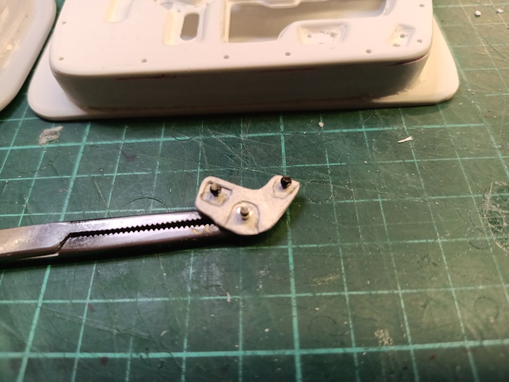
On the left-hand side, the toothed crank holder for the window regulator.
The creation, once again by improvisation. A 5 mm rod clamped in the chuck of the drill and turned out with the flat blade. Finishing and rounding with sandpaper. Finally, I stamped in the teeth with a fine pair of needle-nose pliers and a delicate touch.
No matter how often you check and inspect, you always miss some detail. There is a metal tab in the middle of the lower recess. When I installed it, it looked strange. When I studied the original closely, I discovered another mistake….
So this mistake had to be ironed out. After a minimal correction and a further application of spray filler, the picture was slightly altered.
Not that everything is built perfectly according to the original. The pictures explicitly show this. I have only depicted the various levels of the sheet metal structure in a manner similar to the original. There would have been a lot more to work out. But there is something extraordinary about it and it’s enough for me for the first time. I’ve never built anything like this before, without a printer and freehand. Only from very small photos in very low resolution. But fortunately I at least found these templates on the Internet.
An additional part had to be built before further installations. I used a part that was no longer needed, the roof rack from the Toyota FJ40. I reworked it a little and brought it back to life in a new position.
The rods are adapted to the angle and shape, drilled through and fixed with 1.5 mm silver steel pins. After painting, the dots will probably no longer be visible. Holes in the multi-part component still need to be closed and filled.
This intermediate step was necessary before work can continue on the dashboard and floor assembly. The construction of the self-supporting dashboard support is then based on the existing conditions. There is no conventional dashboard, but an improvisation of the necessary instruments and switches.
Will be continued as soon as possible…
Translation, with the kind support of deepl.com
