English Version
Meine Gefühlswelt, Zweifel über die Machbarkeit und oft auch aufkommende Ideen, lassen mich zwischen meinen Baustellen wechseln. Heute also wieder einmal das Fahrerhaus.
Eine Besonderheit sollte also das Fahrerhaus und das Modell insgesamt weiter aufwerten. Meine Überlegungen führten so zu einem Loch in der Dachhaut.
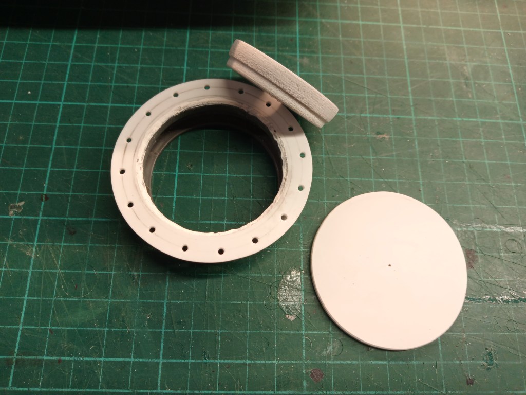
Darauf kam ein Flansch, den ich selbst anfertigte. Drei Kreise führten zum nachfolgenden Ergebnis. Für den Lochkreis habe ich aus dem Durchmesser den Umfang errechnet und durch die Anzahl der Bohrung geteilt. Diese Maß wurde dann mit einem Zirkel auf den Lochkreis übertragen und abschließend gebohrt. Mangels Lochschneidern in passender Größe, habe ich den äußeren Ring mit der Laubsäge herausgearbeitet und rund gefeilt. Feile und Laubsäge kamen auch am Innenring zum Einsatz.
Das Ergebnis. Hier ist auch schon das spätere Ergebnis erkennbar, eine Dachluke für die Fernsicht. Hinter der Luke wird der Anschlagpunkt montiert.
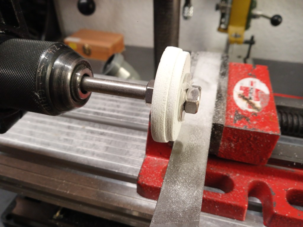
Für die eigentliche Luke musste ich wieder etwas kreativ sein. Zwar hätte ein einfacher Deckel auch genügt, hier sollte aber etwas markantes als Luke dienen. So in Richtung einer U-Boot-Luke. Daher wurde aus Forex mit dem Lochschneider ein Element ausgebohrt. Das wiederum auf einen Gewindestab geschraubt und in die Bohrmaschine eingespannt. Im ersten Schritt eine Fase herstellen…
… und zum Abschluss noch einen abgesetzten Rand eingeschliffen, auf der eingespannten Flachfeile im Schraubstock. Man kann also auch ohne Drehbank Konturen und einen akzeptablen Rundlauf erzielen. So das Ergebnis nach der ersten groben Schleifrunde.
Kombiniert mit einem ebenfalls von Hand rund geschliffenen Deckel, die ersten Teile der Luke.
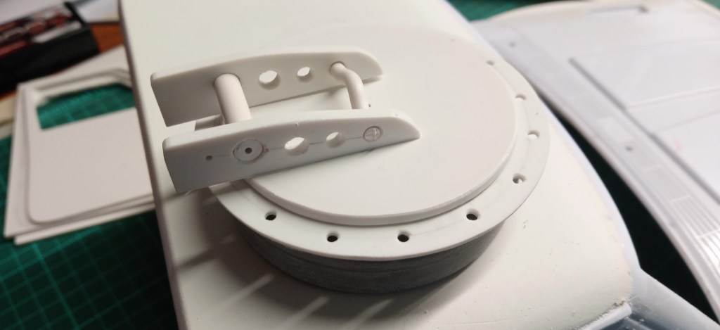
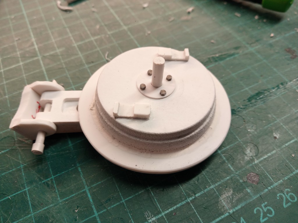
Den ersten Entwurf des Auslegers will ich hier auch präsentieren, der mir aber doch zu wuchtig ausgefallen ist.
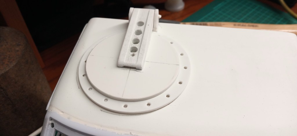
Das zweite Modell gefiel mir dann besser und wurde mit dem Deckel verheiratet.
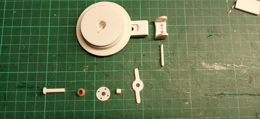
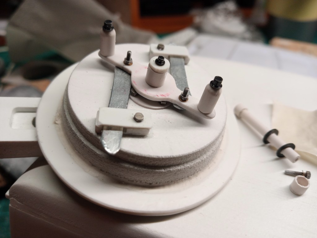
Natürlich soll ja auch alles irgendeine Funktion haben. Es gibt bereits einen Drehpunkt um die Luke aufzustellen, dann braucht es selbstredend auch Technik um es zu verriegeln. Als Lager kam eine 4 mm Tamiya-Lagerbuchse zum Einsatz. In ihr dreht sich ein Kunststoffstift mit einem oberen Rand als Auszugssicherung und Führung. Unten ein Flansch der den Bolzen unter dem Deckel fixiert. Eine weitere Hülse, wird noch durch eine U-Scheibe ersetzt, schafft Abstand zwischen Schraubenköpfen und Verriegelungslaschen.
Aus Zinkblech entstanden die beiden Schließriegel.
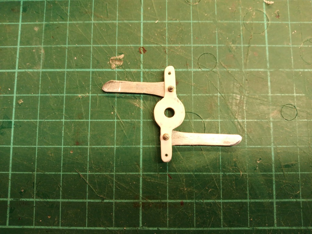
Um die Laschen zu führen, wurde zwei Kleinteile hergestellt und auf der Lukenunterseite verklebt.
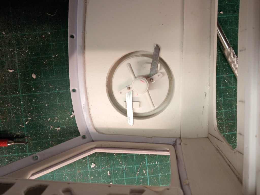
Montiert sieht es im offenen Zustand dann so aus.
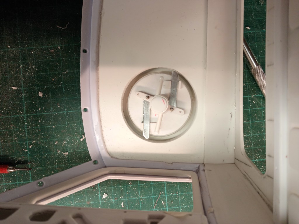
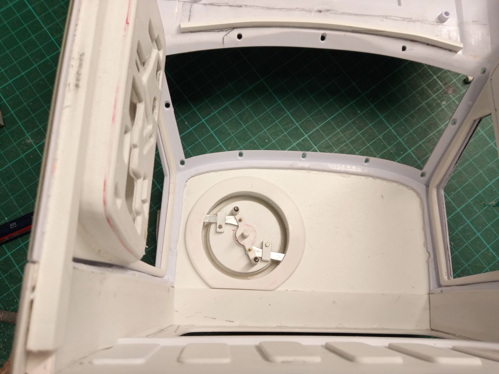
Verriegelt so.
Um den Schiebelaschen einen Platz zu geben, gab es auch noch einen Ring unter dem Dach.

Verriegelt verschwinden nun die Riegel in den Ausfräsungen.
Zum Abschluss Detailbilder des Deckels. Innen wurde die senkrechte Achse mit einer Rohrhülse, Scheibe und einer Schraube M1,2 gesichert. Im Bild auch zu sehen die beiden Handgriffe zur Verriegelung der Luke.
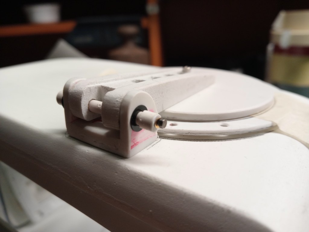
Auch außen war noch eine Sicherungsmaßnahme notwenig. Die Achswelle der Luke bekam ein Rohrstück, dass mit einem Deckel verschlossen und zentriert durchbohrt wurde. Ein Schraube M1,2 sichert den Verschlussdeckel. Somit ist alles bei Bedarf wieder demontierbar.
Während ich das hier schreibe, trocknet die inzwischen lackierte Luke. Sie wurde mit braun grundiert und mit hellgrau überlackiert. Wir werden demnächst sehen, ob alles so geworden ist, wie ich es mir vorstelle.
Wird schnellstmöglich fortgesetzt…
English Version
A hole in the roof?
My emotional world, doubts about the feasibility and often also emerging ideas, make me switch between my construction sites. So today it’s once again the cab.
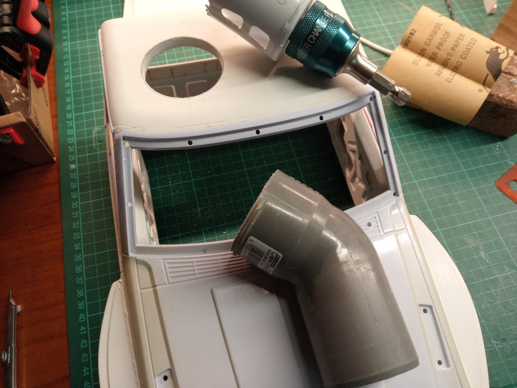
I wanted to add a special feature to enhance the cab and the model as a whole. My thoughts led to a hole in the roof skin.
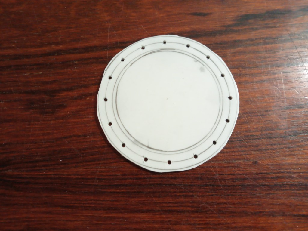
Then came a flange, which I made myself. Three circles led to the following result. For the bolt circle, I calculated the circumference from the diameter and divided it by the number of holes. This measurement was then transferred to the bolt circle with a compass and finally drilled. Due to a lack of hole cutters in a suitable size, I cut out the outer ring with a fretsaw and filed it round. File and fretsaw were also used on the inner ring.
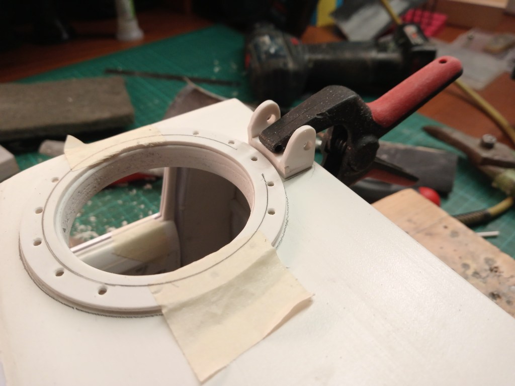
The result. Here you can already see the later result, a roof hatch for the long-distance view. The attachment point is mounted behind the hatch.
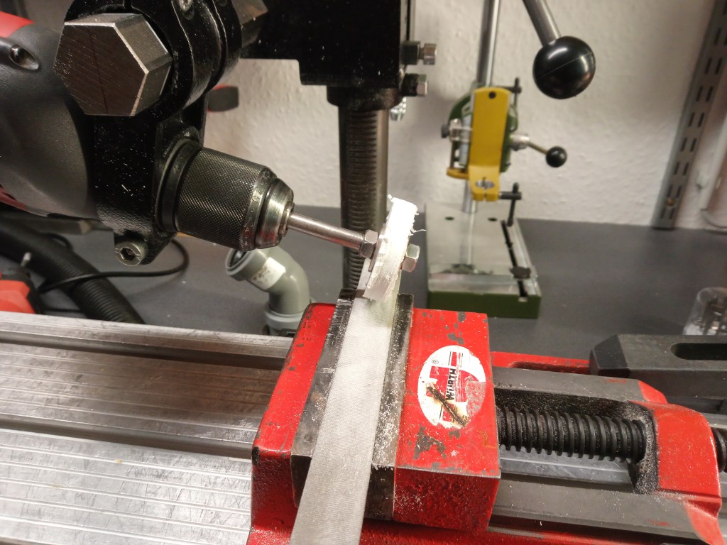
I had to be a bit creative again for the actual hatch. Although a simple cover would have sufficed, I wanted something striking to serve as the hatch. Something along the lines of a submarine hatch. Therefore, an element was drilled out of Forex with a hole cutter. This in turn was screwed onto a threaded rod and clamped in the drill. The first step was to create a chamfer…
… and finally ground a stepped edge on the flat file clamped in the vice. It is therefore possible to achieve contours and acceptable concentricity without a lathe. This is the result after the first rough grinding round.
Combined with a cover that has also been ground round by hand, the first parts of the hatch.
I also want to present the first draft of the boom here, but it turned out too bulky for me.
I liked the second model better and married it to the lid.
Of course, everything should have some kind of function. There is already a pivot point to set up the hatch, then of course it also needs technology to lock it. A 4 mm Tamiya bearing bush was used as the bearing. A plastic pin rotates in it with an upper edge as a pull-out protection and guide. A flange at the bottom fixes the pin under the cover. Another sleeve, which is replaced by a washer, creates a gap between the bolt heads and the locking tab.
The two locking latches were made from sheet zinc.
Two small parts were made to guide the latches and glued to the underside of the hatch.
When assembled, it looks like this when open.
Locked like this.
There was also a ring under the roof to give the sliding latches a place.
When locked, the latches disappear into the cut-outs.
Finally, detailed pictures of the cover. Inside, the vertical axis was secured with a tube sleeve, washer and an M1.2 screw. The picture also shows the two handles for locking the hatch.
Another securing measure was also necessary on the outside. The axle shaft of the hatch was given a piece of pipe that was closed with a cover and drilled through in the center. An M1.2 screw secures the cover. This means that everything can be removed again if necessary.
As I write this, the hatch, which has now been painted, is drying. It was primed with brown and painted over with light gray. We will soon see whether everything has turned out as I imagined.
Will be continued as soon as possible…
Translation, with the kind support of deepl.com
