English Version
Der Rat-Comanche, so der neue Arbeitstitel, steht auf sehr breiter Spur. Das Wort Rat ist die englisch sprachige Bezeichnung für eine Ratte, oder auch ein stark herunter gekommenes Fahrzeug. Mehr Rost als Lack, mit improvisierter Optik und zweckentfremdeten Teilen.
Die hier verwendeten Achsen, werden von Injora als Nachrüstteil für den Axial Wraith angeboten. Mein Comanche hat einen U-Profil-Leiterrahmen. Diese Kombination, so musste ich schnell erkennen, ist nicht kompatibel. Erste Versuche die langen Fahrwerksstreben (Links) des Axial Wraith mit der schmalen Platte des zentralen Verteilergetriebes (Skid Plate) vom SCX10 zu kombinieren, scheiterten an der großen Spreizung. So folgerte ich daraus, dass die Kombination von Wraith Links und der viel breiteren Skid Plate des Wraith eine Lösung sein könnte. Diese Annahme trifft auch tatsächlich zu, dass kann ich vorwegnehmen, aber der SCX10 Leiterrahmen und die Skid Plate sind ebenfalls nicht kompatibel. Was ist darunter zu verstehen? Anhand von Bildern versuche ich das einmal zu erläutern.
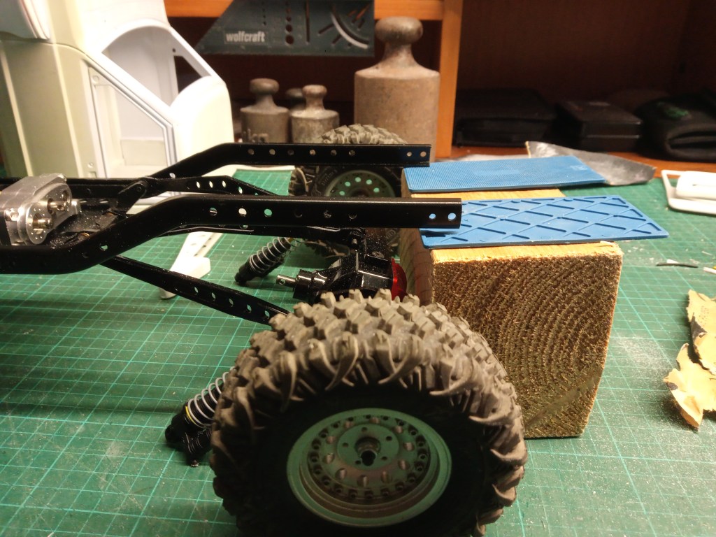
Vorne sieht man, dass die Rundung im Rahmen, nicht zur Position der Achse passt. Dieser Rahmen ist für die langen Wraith Links einfach zu kurz. Der Radstand liegt hier bei ca. 345 mm, beim SCX10 bei 313 mm. Einen einigermaßen genauen Radstand kann ich erst nach dem Einbau aller noch fehlenden Komponenten bestimmen.

Hinten fällt es wegen des gerade verlaufenden Rahmenprofils nicht so stark auf, ist aber je nach geplantem Aufbau und Verwendungszweck, optimal bis zu kurz.
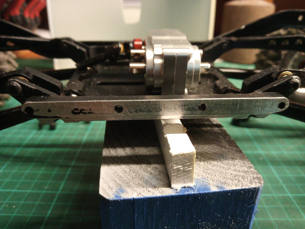
Ein weiteres Problem ist die Breite der Skid Plate. Sie ist fast 3 cm breiter als beim SCX10. Von diesem Modell kommt nämlich der Clone-Stahlrahmen zum Einsatz. Dort wäre das äußere Maß dann 73 mm breit.

Die Verbindung des Leiterrahmens und der Skid Plate wiederum, ist auch nur nach spanabhebenden Maßnahmen möglich. Der Wraith hat ein Gitterrohrchassis, dass mit der Skid Plate und dem Fahrerhaus in der Mitte verschraubt wird. Daher hat die Wraith Skid Plate auch eine unten vorspringende Kante, auf der der Käfig aufgelegt und verschraubt wird. Das jetzt hier detailliert auszuführen, sprengt den Umfang. Daher zeige ich nur was ich gemacht habe, um den U-Profil-Rahmen und die Skid Plate überhaupt miteinander verschrauben zu können.
Am seitlichen Rand der Skid Plate sieht man unterhalb der vier Gewindelöchern noch schwach den schmalen Streifen, auf dem ursprüngliche der Käfig auflag und mit den vier Schrauben befestigt wurde. Das habe ich einfach plan abgefräst und unten leicht angefasst, so dass das U-Profil nunmehr perfekt aufliegen konnte.
Jetzt sind aber noch längst nicht alle Problemstellen beseitigt. Um das zu lösen, habe ich noch einen zweiten Rahmensatz gekauft. Nach dem ermitteln der erforderlichen Maße, wurde der Rahmen in zwei Teile zersägt. Das vordere Teil blieb dabei unangetastet, es wurde lediglich nach vorne verschoben und der hintere Überstand abgesägt. Dazu mussten lediglich zwei kleine Bohrungen, in denen ein Pin der ursprünglichen Skid Plate ruht, aufgebohrt werden. Alle Bohrungen in der Wraith Skid Plate sind im Raster von 3 cm gebohrt. Diese Maße finden sich auch am U-Profil des Rahmens wieder. So muss nur etwas überlegt gesägt werden. Vorne sieht meine Ausführung dann so aus. Im Hintergrund der SCX10 Rahmen in Originallänge und Position. Man sieht auch, dass mit zwei Schrauben der vordere Rahmenteil an der Skid Plate verschraubt wurde. Rechts davon zwei noch freie Schraubenlöcher.
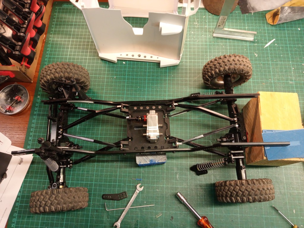
Das zweite Rahmenset wurde nun so abgeschnitten, dass er unmittelbar am vorderen anliegt. In der Aufsicht sieht man den so verlängerten Rahmen. Oben der einteilige kurze Rahmen, unten der zweiteilige aber verlängerte Rahmen. Zurück bleiben so zwei kurze Heckteile und ebensolche gekürzten Frontteile.
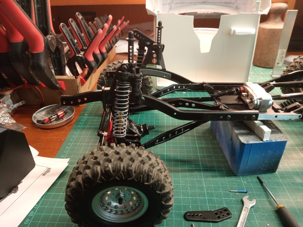
Nun auf beiden Seiten verlängert und mit aufgesetzter Karosserie, Bilder der zukünftigen Basis.
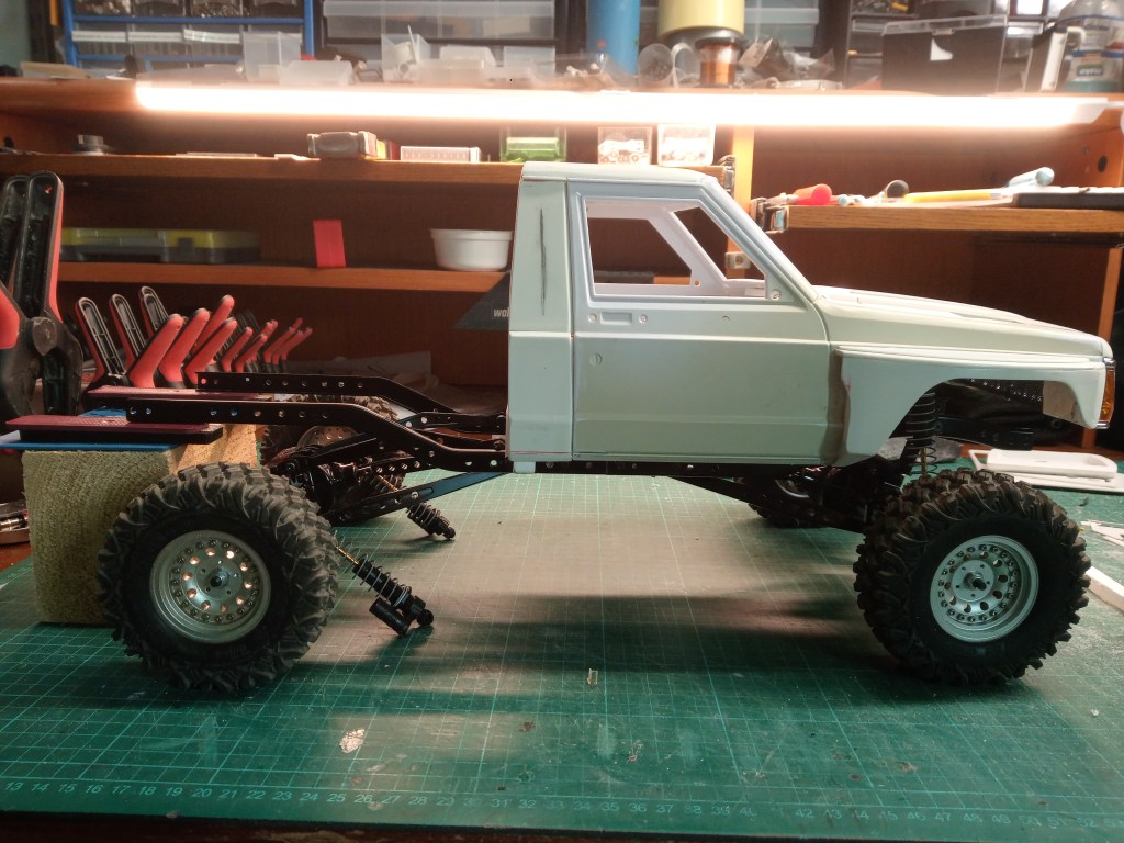
Mit lose aufgesetzter Karosserie, passen die Vorderräder in den Radkasten. Auch die Position der Dämpfer gefällt mir jetzt besser. Vorher musste ich mit einer Traverse, die zu weit hinten sitzenden Dämpferaufnahmen erreichen. So schränkt nun auch kein Rahmenteil den Bewegungsspielraum der Vorderachse mehr ein. Wer außerhalb von fertig konfektionierter Ware baut, hat halt viel zu erzählen…😊

In den nächsten Tagen treffen für vorne noch 100 mm lange Federbeine ein. An der Hinterachse kommt ein Cantileversystem zum Einsatz. Dabei liegt der Dämpfer horizontal zum Rahmen und wird über eine Koppelstange und Umlenkhebel, von der senkrechten in die waagerechte umgelenkt. So ragt kein Dämpfer oder dessen Halterung in den Aufbau.
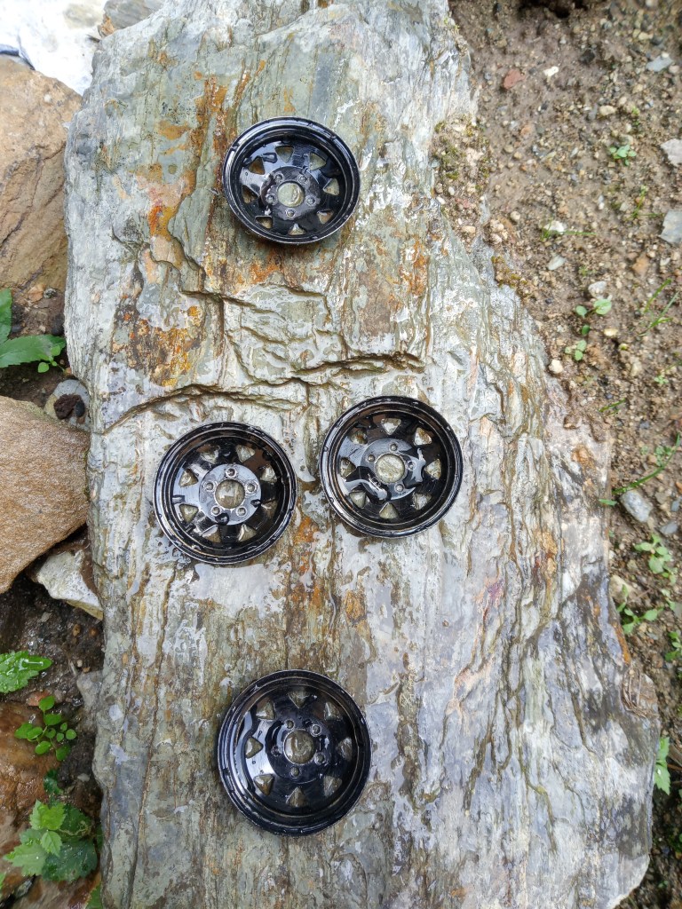
Der später zum Einsatz kommende Radsatz erhält gerade eine Sonderbehandlung. Ein neuer Satz schwarzer Stahlfelgen, wurde mit Schmirgelpapier bearbeitet und liegt bereits seit einer Woche, täglich bewässert, zum Rosten im Freien. Damit habe ich wohl einen neuen Tiefpunkt erreicht…🙄
Ein Ansatz, den ich vielleicht auch dem Stahlrahmenprofil noch antun sollte. Realistischer Modellbau tut manches Mal auch weh…
Wird schnellstmöglich fortgesetzt…
English Version
A very special chassis for the Rat Comanche
The Rat-Comanche, the new working title, has a very wide track. The word rat is the English term for a rat, or a vehicle that has fallen into disrepair. More rust than paint, with an improvised look and misappropriated parts.
The axles used here are offered by Injora as retrofit parts for the Axial Wraith. My Comanche has a U-profile ladder frame. I quickly realized that this combination is not compatible. Initial attempts to combine the long chassis struts (links) of the Axial Wraith with the narrow plate of the central transfer case (skid plate) of the SCX10 failed due to the large spread. So I concluded that the combination of Wraith Links and the much wider skid plate of the Wraith could be a solution. This assumption is actually correct, I can say that in advance, but the SCX10 ladder frame and the skid plate are also not compatible. What does this mean? I will try to explain this with the help of pictures.
At the front you can see that the curve in the frame does not match the position of the axle. This frame is simply too short for the long Wraith links. The wheelbase here is approx 345 mm, with the SCX10 it is 313 mm. I can only determine a reasonably accurate wheelbase once all the missing components have been fitted.
It is not so noticeable at the rear due to the straight frame profile, but depending on the planned set-up and intended use, it is ideal or even too short.
Another problem is the width of the skid plate. It is almost 3 cm wider than on the SCX10. This is because the Clone steel frame is used for this model. The outer dimension would then be 73 mm wide.
The connection between the ladder frame and the skid plate is also only possible after machining. The Wraith has a tubular lattice chassis that is bolted to the skid plate and the cab in the middle. This is why the Wraith skid plate also has a protruding edge at the bottom, on which the cage is placed and bolted. It would go beyond the scope of this article to go into detail here. I will therefore only show what I did to be able to screw the U-profile frame and the skid plate together.
On the side edge of the skid plate, below the four threaded holes, you can still see the narrow strip on which the cage originally rested and was fastened with the four screws. I simply milled it flat and touched it slightly at the bottom so that the U-profile could now rest perfectly.
But not all the problems have been solved yet. To solve this, I bought a second set of frames. After determining the required dimensions, the frame was sawn into two parts. The front part remained untouched, it was simply moved to the front and the rear overhang sawed off. To do this, only two small holes, in which a pin of the original skid plate rests, had to be drilled out. All holes in the Wraith skid plate are drilled at 3 cm intervals. These dimensions can also be found on the U-profile of the frame. So you only have to saw a little carefully. My design looks like this at the front. In the background is the SCX10 frame in its original length and position. You can also see that the front part of the frame was screwed to the skid plate with two screws. To the right of this are two free screw holes.
The second frame set has now been cut off so that it lies directly against the front frame. The top view shows the extended frame. Above the one-piece short frame, below the two-piece but extended frame. This leaves two short rear parts and the same shortened front parts.
Now extended on both sides and with the body attached, pictures of the future base.
The front wheels fit into the wheel arch with the body mounted loosely. I also like the position of the shock absorbers better now. Previously, I had to use a cross member to reach the shock absorber mounts, which were too far back. Now there is no longer any frame part restricting the range of movement of the front axle. Anyone who builds outside of ready-made goods has a lot to tell…😊
In the next few days, 100 mm long struts will arrive for the front. A cantilever system will be used on the rear axle. The damper is horizontal to the frame and is deflected from vertical to horizontal via a coupling rod and bellcrank. This means that no damper or its mounting protrudes into the body.
The wheel set to be used later is currently undergoing special treatment. A new set of black steel rims has been treated with sandpaper and has been lying outside for a week, watered daily, to rust. So I’ve probably reached a new low…🙄
An approach that I should perhaps also do to the steel frame profile. Realistic model building sometimes hurts too…
Will be continued as soon as possible…
Translation, with the kind support of deepl.com
