Quellen: Internet Bildersuche
English Version
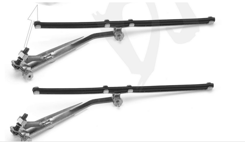
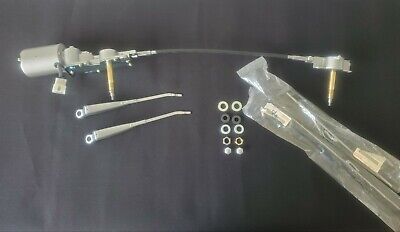
Gerade begeistert mich der sich dynamisch entwickelte Zustand des Toyota Modells immer wieder aufs Neue. Ich suche geradezu nach Herausforderungen und so richtig kann mich derzeit auch nichts wirklich zurückhalten. So begann ich die Tage erste Anbauteile zu modifizieren. Hier die einteiligen Kunststoff-Scheibenwischer der Baukastenausführung. Bis ich vor einigen Tagen im Rockcrawler-Forum vorgestellten Metall-Scheibenwischer eines Kollegen sah. Im Internet werden diese lasergeschnitten Scheibenwischer aus Metall angeboten. Mehrere Einzelteile, einschließlich einer Feder, für die Vorspannung und Befestigungsschrauben. Zugegeben eine reizvolle Variante, aber die Biegung ist auf Fahrzeuge mit größerer Scheibe und unterem Drehpunkt vorgesehen. Nachfolgend ein solches Modell als Beispiel.
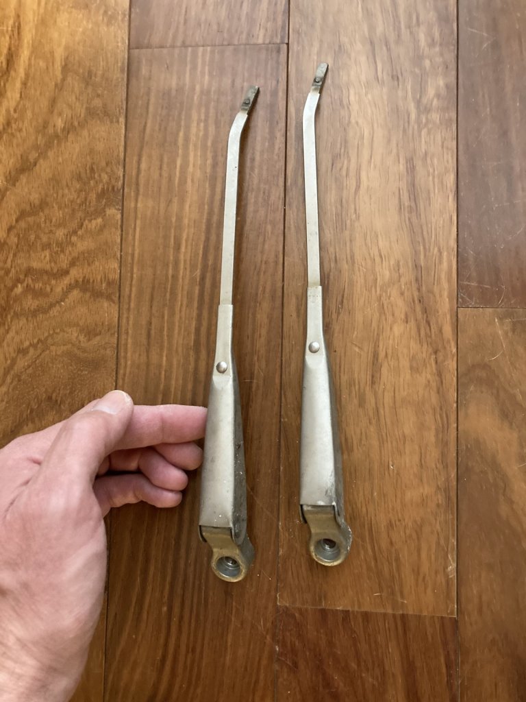
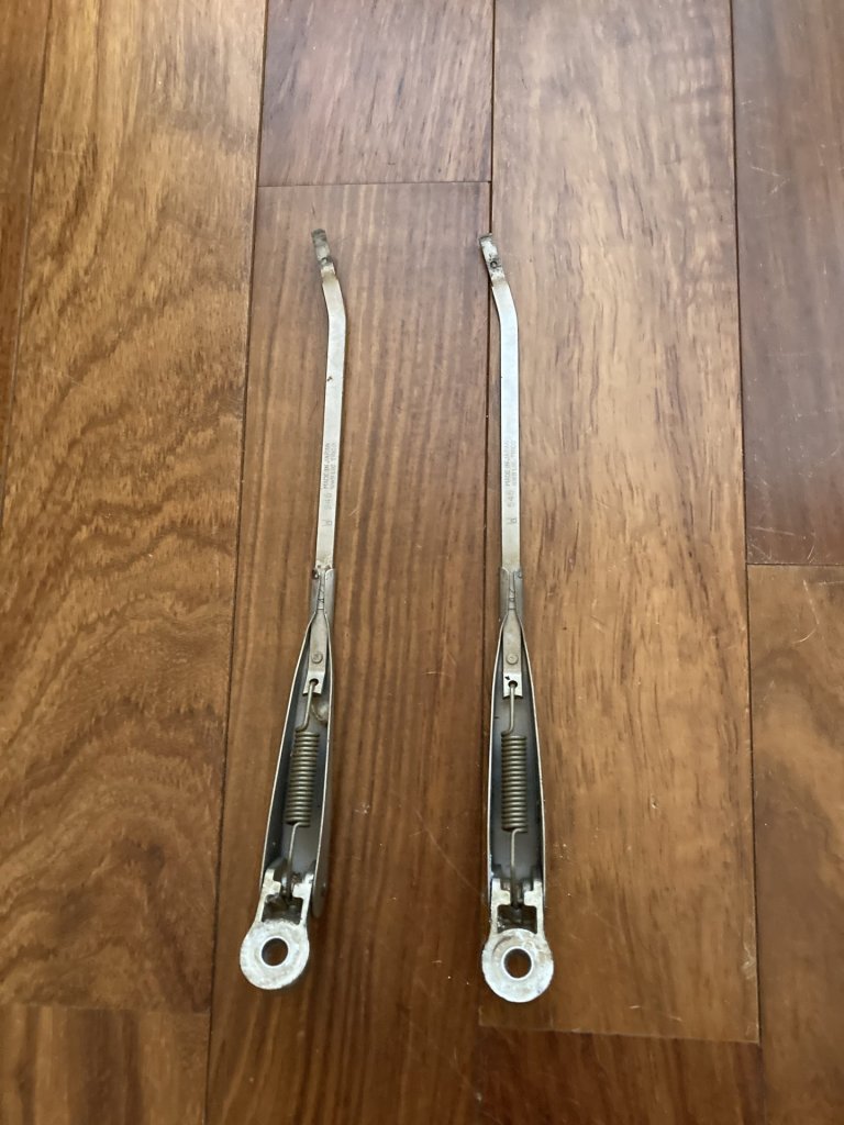
Bei genauer Betrachtung, fand ich sie dann optisch doch nicht so gelungen. Mir schwebte jetzt ein Eigenbau vor. In meinem Fundus gibt es inzwischen eine gut sortierte Auswahl, verschiedenster Materialen. Zwei Materialien befand ich für mein Vorhaben als besonders geeignet. Einen 5 mm dünnen weichen Aluminiumstab und ein Alublech 0,3 mm stark und in halbharter Ausführung. Es ist fast problemlos mit den Händen formbar. Nach der Größenbestimmung suchte ich mir eine entsprechende Vorlage im Internet. Das war sie also, meine Vorlage.
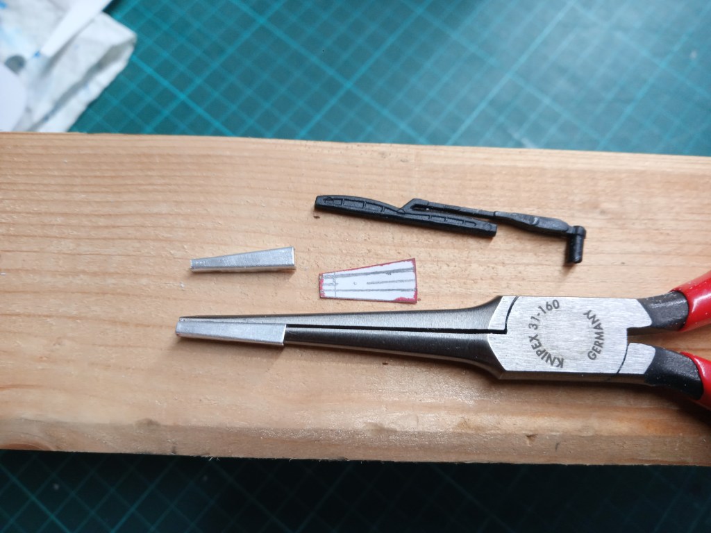
Wie bei vielen meiner Eigenbauten, war auch hier eine Abwicklung aus Papier die Grundlage. Diese Vorlage war aber im Vergleich zu den bisherigen etwas kleiner. Hier in der Bildmitte zu sehen. Daraus wurde mit einer konventionellen Haushaltsschere das Alu-Teil ausgeschnitten. Im Weiteren auch eine lange Flachzange, mit der das Aluminiumblech gebogen wurde. Ebenfalls die zwei so entstandenen Wischer-Unterteile, fertig gebogen.
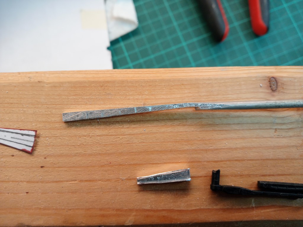
Weiter ging es mit der Herstellung des Gestänges, an dem der eigentliche Wischer befestigt wird. Dazu wurde der Alu-Rundstab, auf dem Schraubstock, mit dem Hammer, in eine flache Form geschlagen. Im Folgenden gab es noch mehrere Bearbeitungsschritte mit der Feile, um das verdichtete Material in seine spätere Form zu bringen.
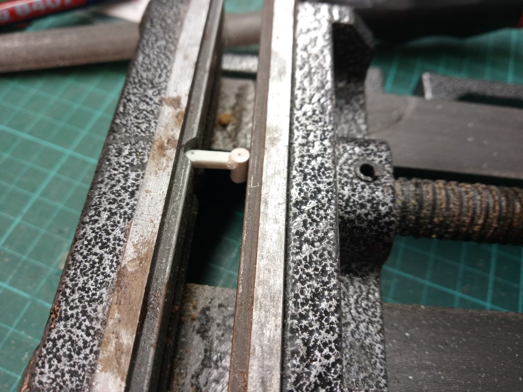
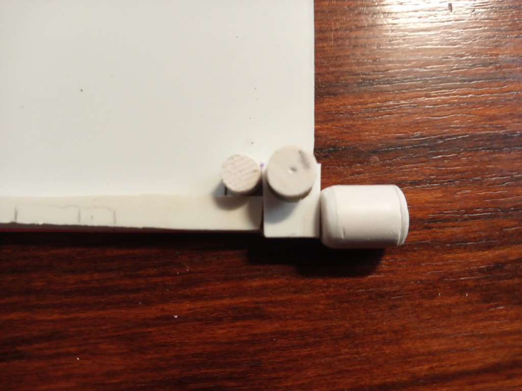
Der nächste Bauschritt betraf den Drehpunkt des Wischerarms. Für dessen Herstellung wählte ich wieder Kunststoff. Einmal weil ich entsprechendes Material verfügbar hatte und weil ein solch kleines Teil damit leichter zu bearbeiten ist. So fanden schließlich ein rechteckiges und ein rundes Teil zusammen. Im Schraubstock bis zum Aushärten der Klebestelle fixiert.
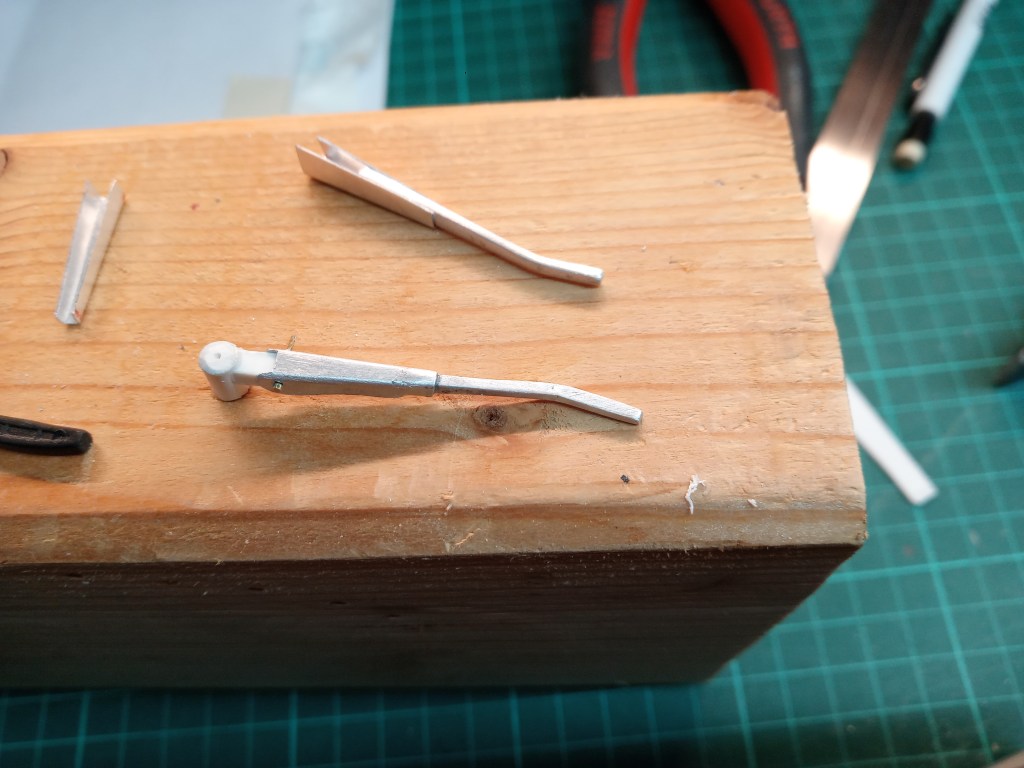
Dieses Teil bildet von nun an das erste Teil des Wischers. Den Drehpunkt und auch gleichzeitig die Klappfunktion. Hier bereits mit einer kleinen Schraube M 0,6 verbunden. Das Gestänge wurde auch schon im Winkel gebogen. Gestänge und Unterteil wurden mit Sekundenkleber dauerhaft fixiert. So die 3-teilige Baugruppe vor dem Einbau.
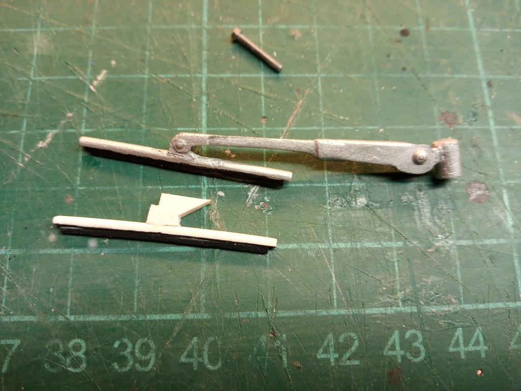
Der eigentliche Wischergummi geriet etwas aufwändiger. Ein Rundstab wurde abgefräst. Ein Halbrundprofil geht natürlich auch, hatte ich aber gerade nicht verfügbar. Ein 0,5 mm PS-Streifen, als eigentlicher Wischergummi, wurde winklig darauf festgeklebt. Für die Befestigung des Wischergummis am Arm wurde noch eine Halterung benötigt, die aufwändig bearbeitet, mit einem 0,3 mm dünnen Blech verschraubt wurde. Alles an die Bügelform angepasst und damit verklebt.
… und so komplett am Fahrzeug…

Dazu gibt es eine Innenseite. Bei diesem frühen FJ40-Modell war der Wischermotor noch freiliegend am oberen Fensterrahmen montiert. Auf der Beifahrerseite sitzt der Motor mit Getriebe und einem wellenbetriebenen Ausgang zur Fahrerseite. Dort sitzt lediglich ein kleines Umlenkgetriebe, das den dortigen Wischerarm antreibt. So sieht das in der Realität aus.
Mein Nachbau bestand aus vielen Einzelteilen, 16 Stück in Summe. Das fing so an.
Bauteil um Bauteil entwickelte sich die Einheit…
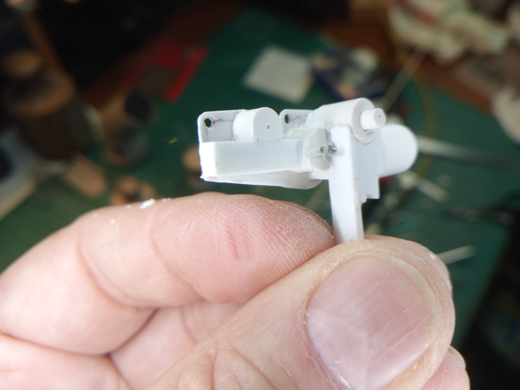
… zu einer fast fertiggestellten kompletten Antriebseinheit. Kleine Schrauben M1,2 und M 0,6 sind auch mit verbaut, um eine möglichst realistische Optik zu schaffen.
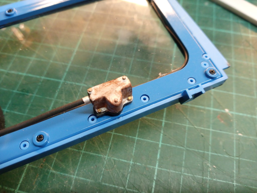
Das Gegenstück auf der Fahrerseite hat schon etwas Patina angesetzt. Fünf kleine M 0,6 Schrauben sind als optische Blickfänger mit verbaut. Mit zwei davon ist die Antriebseinheit mit dem Fensterrahmen verschraubt.
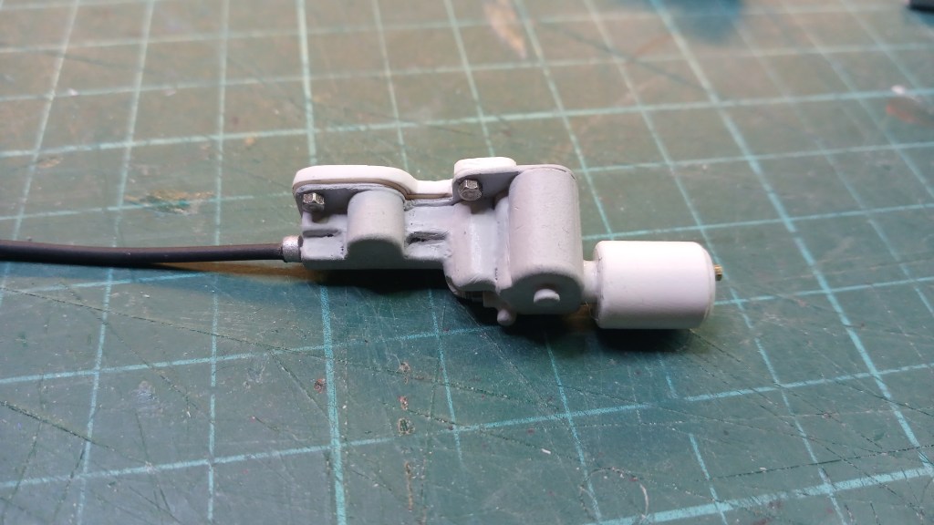
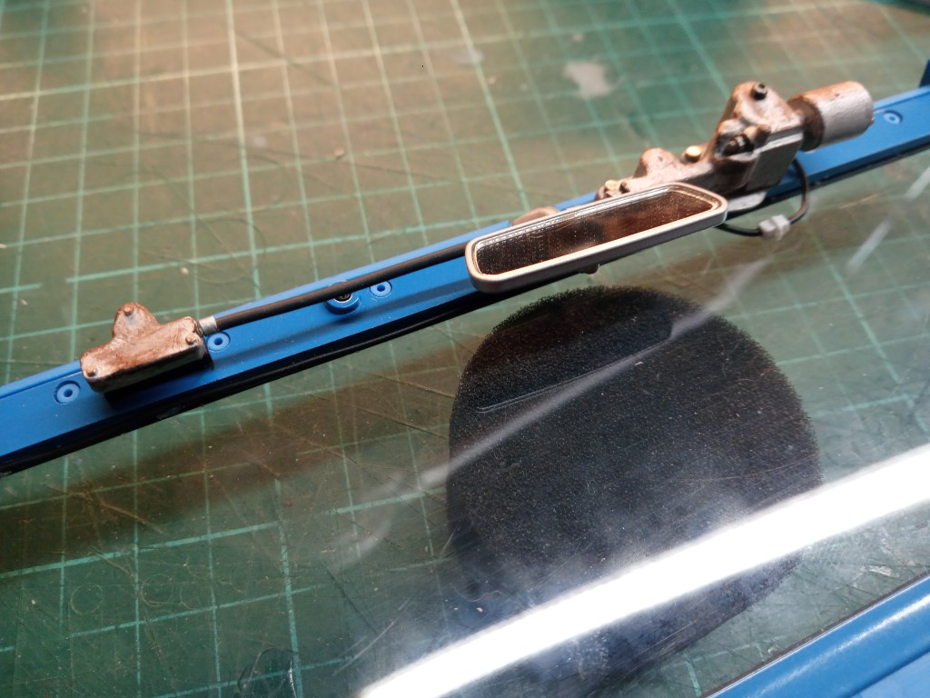
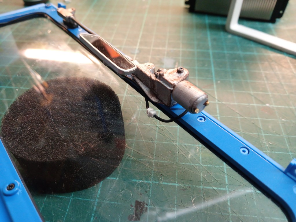
Final geschliffen, lackiert und mit den obligatorischen Gebrauchsspuren versehen, die Antriebseinheit mit montiertem Wellenantrieb, auf der Fahrerseite.
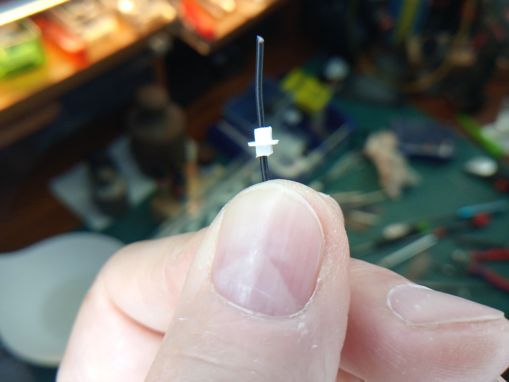
Als zusätzliche Aufwertung gab es noch einen Elektroanschluss am Motor. Optisch ganz dem Original nachempfunden, hier aber nur als Attrappe. Ein kleiner Quader und ein ausgeklinkter 0,5 mm PS-Rest machen die Illusion fast schon perfekt. Hier noch der Rohbau, der noch final beigeschliffen wurde.
Wird schnellstmöglich fortgesetzt…
English Version
Do-it-yourself windshield wipers
Sources: Internet image search
At the moment, I’m constantly inspired by the dynamic development of the Toyota model. I’m really looking for challenges and nothing can really hold me back at the moment. So the other day I started to modify the first add-on parts. Here are the one-piece plastic windshield wipers in the kit version. Until I saw the metal windshield wipers presented by a colleague in the Rockcrawler forum a few days ago. These laser-cut metal windshield wipers are offered on the Internet. Several individual parts, including a spring for the preload and fastening screws. Admittedly an attractive variant, but the bend is intended for vehicles with a larger windshield and lower pivot point. Below is an example of such a model.
On closer inspection, I didn’t think it looked so good after all. I was now thinking of building one myself. I now have a well-assorted selection of different materials in my stock. I found two materials to be particularly suitable for my project. A 5 mm thin, soft aluminum rod and a 0.3 mm thick, semi-hard aluminum sheet. It is almost easy to shape with your hands. After determining the size, I looked for a suitable template on the Internet. So this was my template.
As with many of my own designs, this was also based on a paper template. However, this template was somewhat smaller than the previous ones. You can see it in the center of the picture. The aluminum part was cut out of it with conventional household scissors. A long pair of flat-nose pliers was also used to bend the aluminum sheet. The two lower parts of the wiper created in this way were also bent.
The next step was to make the linkage to which the actual wiper is attached. To do this, the aluminum round bar was hammered into a flat shape on the vice. This was followed by several processing steps with a file to shape the compacted material into its final form.
The next construction step involved the pivot point of the wiper arm. I chose plastic again to make it. Firstly because I had the right material available and secondly because such a small part is easier to work with. In the end, a rectangular and a round part came together. Fixed in a vice until the glue had hardened.
From now on, this part will form the first part of the wiper. The pivot point and also the folding function. Here already connected with a small M 0.6 screw. The linkage has already been bent at an angle. The linkage and lower part were permanently fixed with superglue. The 3-part assembly before installation.
The actual wiper rubber turned out to be somewhat more complex. A round bar was milled off. A half-round profile would of course also work, but I didn’t have one available at the time. A 0.5 mm PS strip, as the actual wiper rubber, was glued to it at an angle. A bracket was needed to attach the wiper rubber to the arm, which was elaborately machined and screwed to a 0.3 mm thin sheet of metal. Everything was adapted to the shape of the bracket and glued to it.
… and so complete on the vehicle…
There is also an inside. On this early FJ40 model, the wiper motor was still exposed on the upper window frame. The motor with gearbox and a shaft-driven output to the driver’s side is located on the passenger side. Only a small reversing gear is located there, which drives the wiper arm there. This is what it looks like in reality.
My replica consisted of many individual parts, 16 in total. It started like this.
Component by component, the unit developed…
… to an almost complete drive unit. Small M1.2 and M0.6 screws are also used to create the most realistic look possible.
The counterpart on the driver’s side has already acquired a little patina. Five small M 0.6 screws are included as visual eye-catchers. Two of these are used to screw the drive unit to the window frame
Finally sanded, painted and with the obligatory signs of wear, the drive unit with mounted shaft drive on the driver’s side.
As an additional upgrade, there was also an electrical connection to the motor. Visually based entirely on the original, but here only as a dummy. A small cuboid and a notched 0.5 mm PS rest make the illusion almost perfect. Here is the body shell, which has just been sanded.
Will be continued as soon as possible…
Translation, with the kind support of deepl.com
