Quellen: Internet Bildersuche
English Version
Beim Einschlafen verarbeite ich des Öfteren meine Tageseindrücke. Manchmal kommen mir dabei auch irgendwelche Ideen in den Sinn. So begann auch diese Baustelle zunächst nur in meinen Gedanken. Mit etwas Verzögerung starte ich schließlich die Nachtruhe, das am folgenden Tag mit einer intensiven Recherche ihren weiteren Verlauf nahm. Könnte mein Toyota einen Überrollbügel bekommen? Er ist ja komplett zerlegbar und so auch praktisch offen zu fahren.
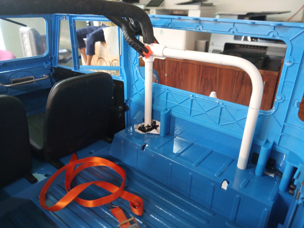
In einem Forumsbeitrag fand ich die benötigten Maße des Originalbügels, 2 Zoll, entsprechend 50 mm im Durchmesser. Ein Foto wurde von mir auf den Maßstab skaliert und die äußere Kontur auf Papier übertragen.
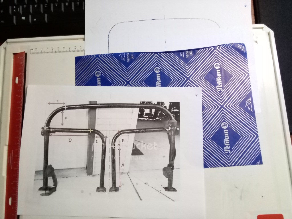
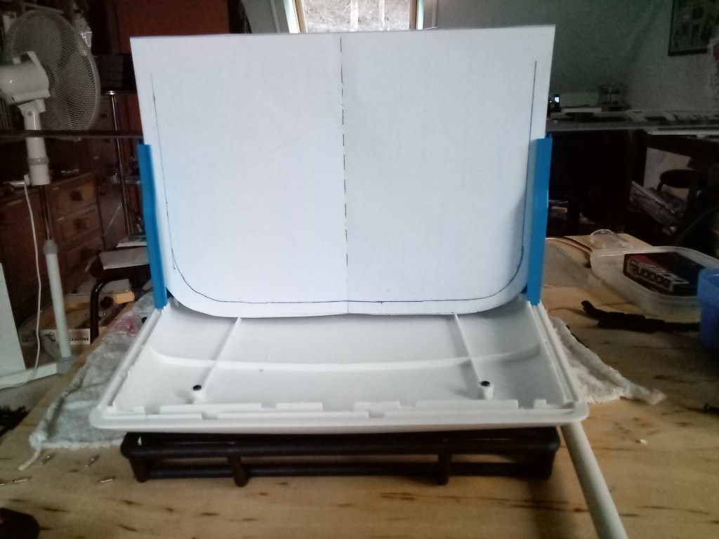
Damit wurde eine erste Anprobe im Innenraum durchgeführt. An dieser Stelle möchte ich noch einmal betonen, wie exakt FMS sich hier an den Maßen des Originals orientiert hat. Es waren nahezu keine Korrekturen erforderlich.
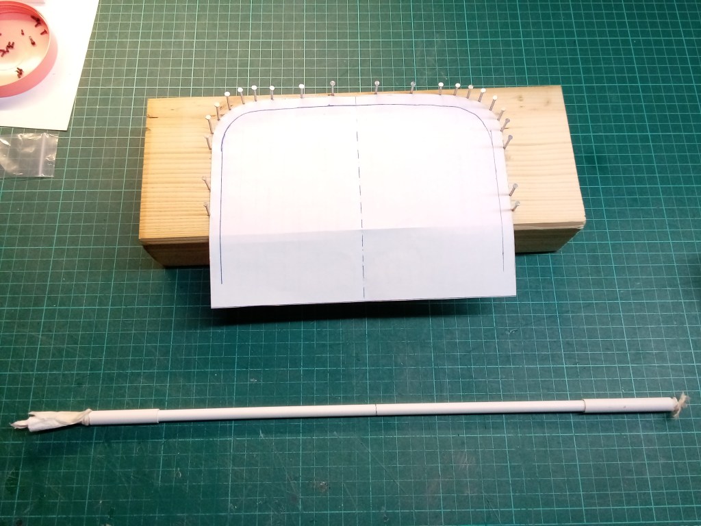
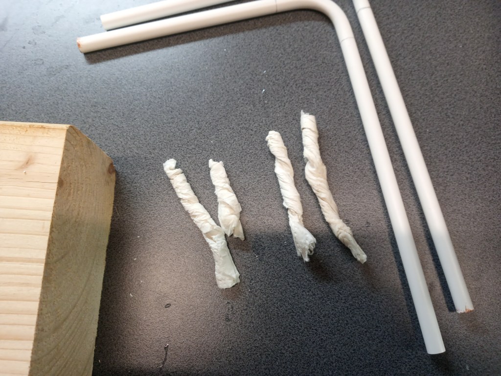
Anhand der Papierschablone konnte auf einen Holzbrett mit Nägeln, der spätere äußere Rand fixiert werden. Praktisch die innere Kontur des Fahrerhauses. Am unteren Bildrand das Kunststoffrohr, 8,0 mm im Aussendurchmesser. Es wurde zunächst einseitig mit Papier verstopft, mit verdichtetem Quarzsand gefüllt und die Füllseite ebenfalls mit Papier verschlossen. Alles gemeinsam noch einmal mit einem passenden Stab verdichten, bis nichts mehr nachgibt. Das ist sehr wichtig, weil es sonst beim Biegen zu Verformungen kommen kann.
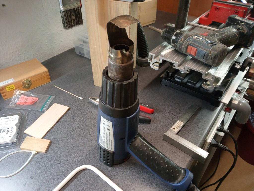
Das anwärmen der Biegelänge erfolgte bei mir mit einem temperaturgeregelten Heißluftgebläse bei 150°C und einem Aufsatz für die optimale Wärmeführung. Gute Voraussetzungen, aber ein erster Versuch scheiterte, wegen ungenügendem Aufheizen, der zuvor berechneten Anwärmlänge. Am unteren Bildrand ist dieses Ergebnis auch noch zu sehen.
Biegt man nur einen Bogen und schneidet dann die Enden auf Länge, genügt das Anwärmen nach Gefühl. Im schlechtesten Fall wird dabei der Bogen zu klein oder ungleichmäßig. Bei einem Bügel müssen aber Maße eingehalten werden und da hilft die Formel für die Anwärmlänge.
Anwärmelänge = Biegeradius in Grad / 360° x 2 x Radius x Phi
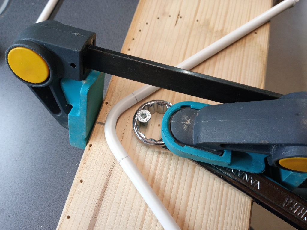
Als weitere Hilfsmittel kamen dem Radius entsprechende Ringschlüssel zum Einsatz.
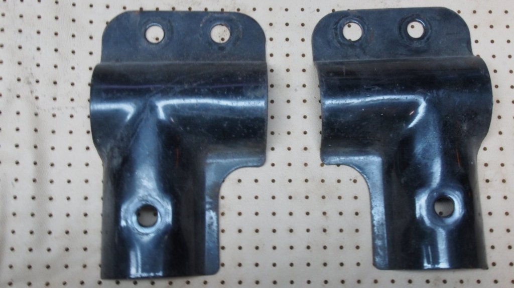
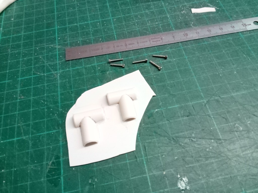
Vor dem weiteren Bauverlauf, ein Foto der originalen Verbindungsmuffen. Sie verbinden mit Schrauben den Hauptbügel, mit den beiden nach hinten verlaufenden Stützbügeln.
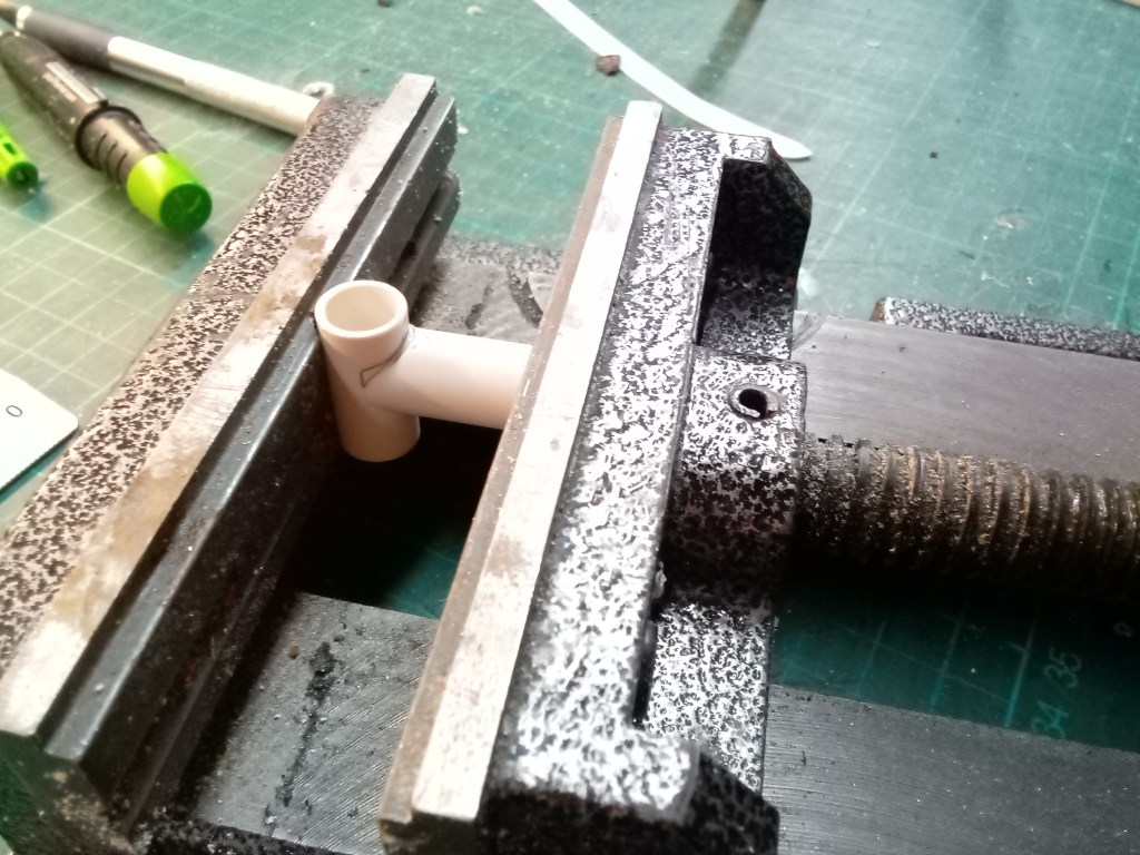
Deren Nachbau forderte mich etwas heraus. Ein 10 mm Kunststoffrohr wurde auf Länge gesägt und mit einem 8 mm Halbrundfräser so angepasst, dass sie perfekt zueinander passen.

Das alles, um im nächsten Schritt wieder zersägt zu werden. Es werden jeweils zwei Halbschalen benötigt.
Da so die Optik noch nicht stimmte, wurden die Hälften wieder auf 0,5 mm PS Reste aufgeklebt…
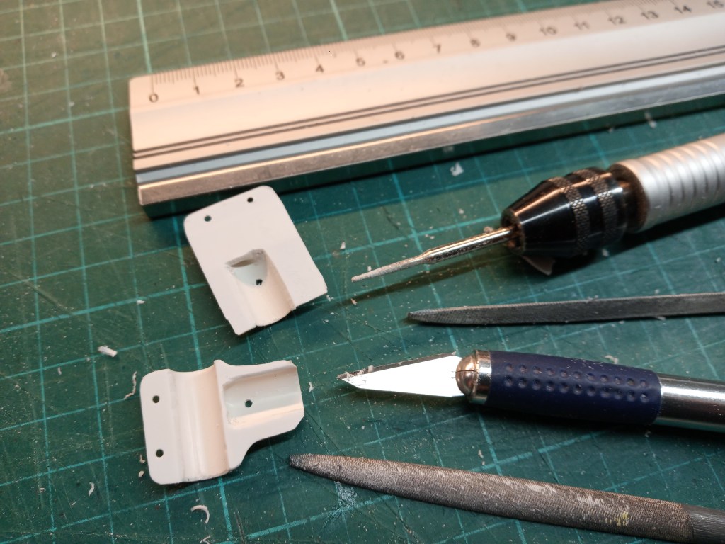
… um in Folge wieder von einem Großteil befreit zu werden. Das klingt einfacher, als es in Wirklichkeit der Fall war. Auf der Größe einer Briefmarke, wurde mit verschiedensten Werkzeugen die spätere Form wieder herausgearbeitet. Auf dem rechten Foto das vorläufige Ergebnis, die Verbindungsmuffe.
Montiert dann dieses Bild. Hier wurde der Bügel schon im Kopfbereich mit einem Polster aus Moosgummi beklebt.

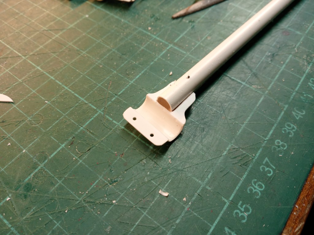
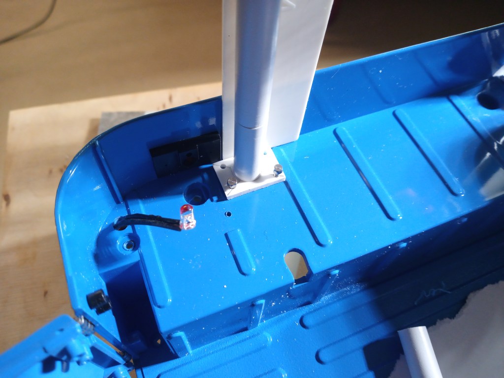
Im Folgenden einige Bilder der weiteren Bauteile, wie die hinteren Stützbügel und die vier Befestigungsflansche auf dem Bodenblech.
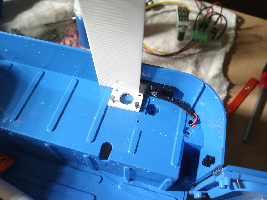
Um ein möglichst realistisches Bild zu bekommen, wurde der Bügel mit insgesamt 16 Schrauben M 1,6 und vier Platten am Boden verschraubt. Darin der Bügel verklebt. So verklebt steht alles wie gewünscht.
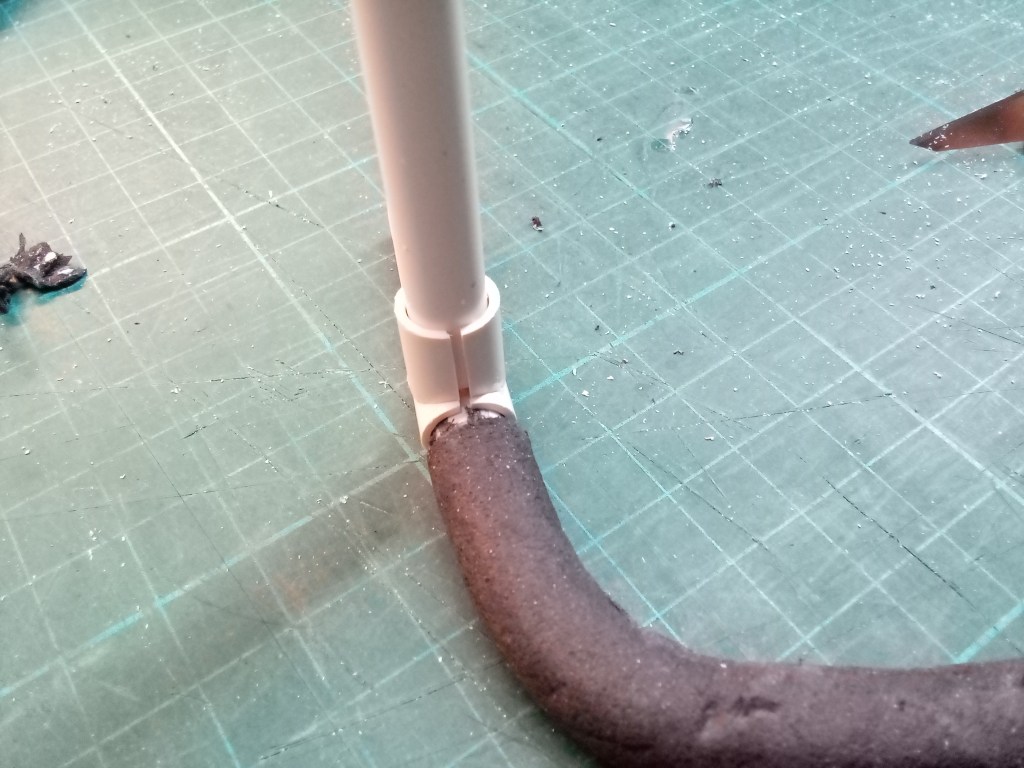
Eine Frage beschäftigte mich aber schon immer. Kann man eine Schweißnaht auch in einen Modellmaßstab übertragen, bzw. überhaupt nachstellen. Für die Reparatur kleiner Fehlstellen hatte ich mir eine Tube Vallejo Plastic Putty zugelegt. Eine Art plastischer Kit, mit langer, spitzer Düse, für punktgenaues Auftragen. Als Folge dieses Versuches, das nächste Bild.
Eine Schweißnaht im Maßstab 1/6,7. Besser war sie leider nicht auf das Bild zu bringen. Die Reflektionen in Verbindung mit meiner Handykamera habe es nicht besser geschafft. Unter dem Strich aber ein sehr erfreuliches Ergebnis, dass meinen Vorstellungen eines möglichst realistischen Modells sehr nahekommt.

Das Gesamtergebnis, lackiert und komplett verschraubt.
Wird schnellstmöglich fortgesetzt…
English Version
Build your own roll bar for the FJ40
Sources: Internet image search
When I fall asleep, I often process my impressions of the day. Sometimes some ideas come to mind. So this construction site also began in my mind at first. After a bit of a delay, I finally went to sleep, which was followed by intensive research the next day. Could my Toyota be fitted with a roll bar? After all, it can be completely dismantled and is therefore practical to drive open.
In a forum post, I found the required dimensions of the original bar, 2 inches, corresponding to 50 mm in diameter. I scaled a photo to the required size and transferred the outer contour onto paper.
This was used to carry out an initial fitting in the interior. At this point, I would like to emphasize once again how precisely FMS followed the dimensions of the original. Almost no corrections were necessary.
The paper template was used to fix the later outer edge to a wooden board with nails. Practically the inner contour of the cab. At the bottom of the picture is the plastic tube, 8.0 mm in outer diameter. It was first plugged on one side with paper, filled with compacted quartz sand and the filling side also sealed with paper. Compact everything together again with a suitable rod until nothing gives way. This is very important because otherwise deformation can occur during bending.
I heated the bending length with a temperature-controlled hot air blower at 150°C and an attachment for optimum heat conduction. Good conditions, but a first attempt failed due to insufficient heating of the previously calculated heating length. This result can also be seen at the bottom of the picture.
If you only bend one bend and then cut the ends to length, heating by feel is sufficient. In the worst case, the bend will be too small or uneven. With a stirrup, however, dimensions must be maintained and the formula for the heating length helps here.
Heating length = bending radius in degrees / 360° x 2 x radius x Phi
Other tools used were ring wrenches corresponding to the radius.
Before continuing with the construction process, a photo of the original connecting sleeves. They connect the main bracket to the two support brackets running to the rear with screws.
Rebuilding them was a bit of a challenge. A 10 mm plastic tube was sawn to length and adjusted with an 8 mm half-round cutter so that they fit together perfectly.
All this to be sawn up again in the next step. Two half shells are needed for each.
As the look was not yet right, the halves were glued back onto 0.5 mm PS remnants…
… in order to be freed from a large part of it again. That sounds easier than it actually was. On the size of a postage stamp, the later shape was worked out again using various tools. The photo on the right shows the preliminary result, the connecting sleeve.
Assembled then this picture. Here, the head of the bracket has already been covered with a foam rubber pad.
Below are some pictures of the other components, such as the rear support brackets and the four mounting flanges on the floor panel.
To get as realistic a picture as possible, the bracket was screwed to the floor with a total of 16 M 1.6 screws and four plates. The bracket was glued inside. Glued in this way, everything stands as desired.
However, I have always had one question on my mind. Is it possible to transfer a weld seam to a model scale or to adjust it at all? I had bought a tube of Vallejo Plastic Putty to repair small imperfections. A kind of plastic kit with a long, pointed nozzle for precise application. As a result of this attempt, the next picture.
A weld seam on a scale of 1/6.7. Unfortunately, I couldn’t get it any better on the picture. The reflections in conjunction with my cell phone camera didn’t make it any better. All in all, however, a very pleasing result that comes very close to my idea of a model that is as realistic as possible.
The overall result, painted and completely screwed together.
Will be continued as soon as possible…
Translation, with the kind support of deepl.com
