Quellen: Internet Bildersuche, Pattex Kleber
English Version
Wieder schon lange nichts mehr geschrieben. Meine private Haus-Baustelle hält mich derzeit gänzlich vom Modellbau ab. Dennoch ist in der Zeit nach Weihnachten einiges gebaut worden. Das will ich aber gerne vorstellen.
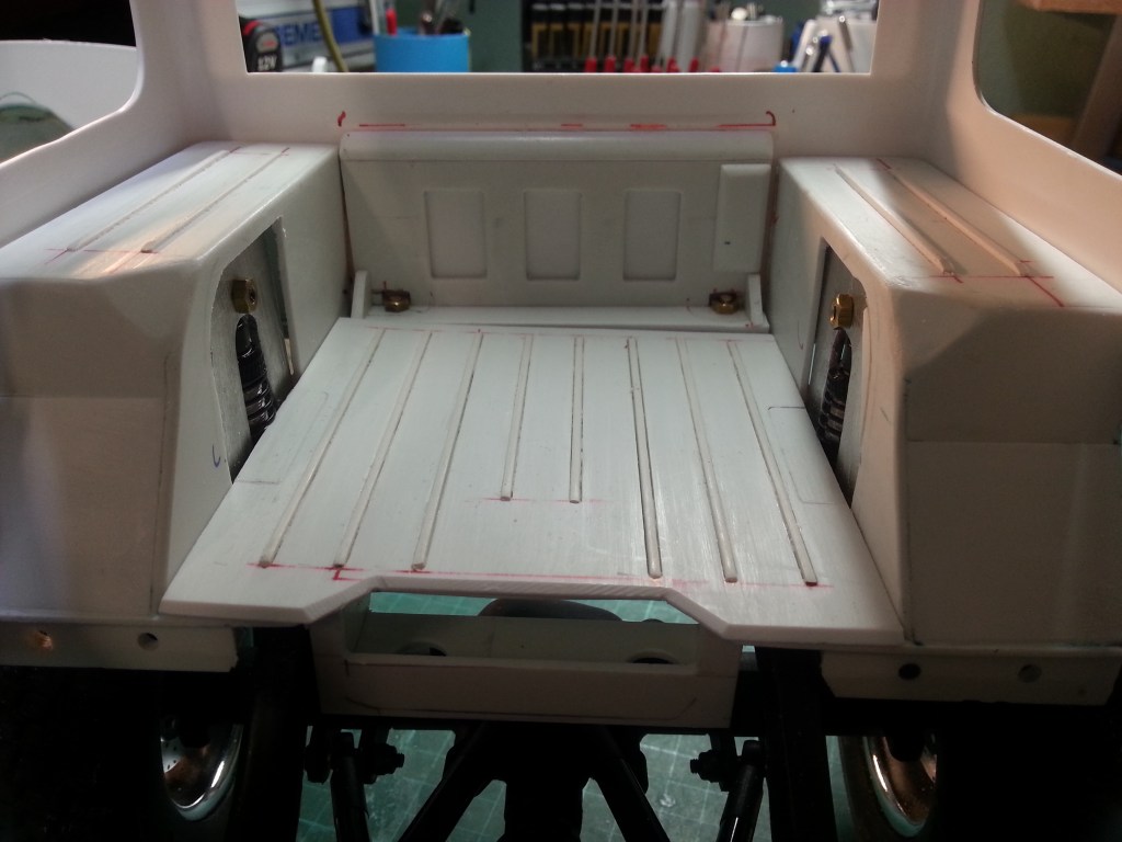
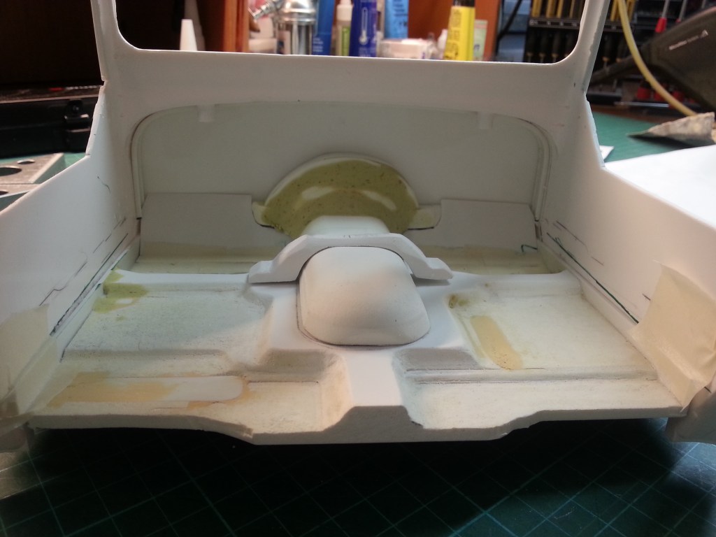
Hier also die bisher gemachten Fortschritte, beim Bau meines Wranglers. Begonnen hatte ich mit der weiteren Gestaltung des Laderaums. Dem Vorbild entsprechend, sollten der Boden und die Oberseiten der Kotflügel eine Struktur bekommen. Nach Bilder-Vorlage wurde die Anzahl Blechsicken in gleichmäßigem Abstand auf die Oberflächen aufgezeichnet. Mit einem Fräser auf dem Koordinatentisch Nuten gefräst und darin PS-Streifen 1,5 x 1,5 mm verklebt.
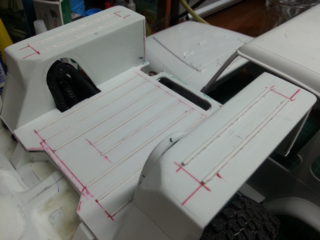
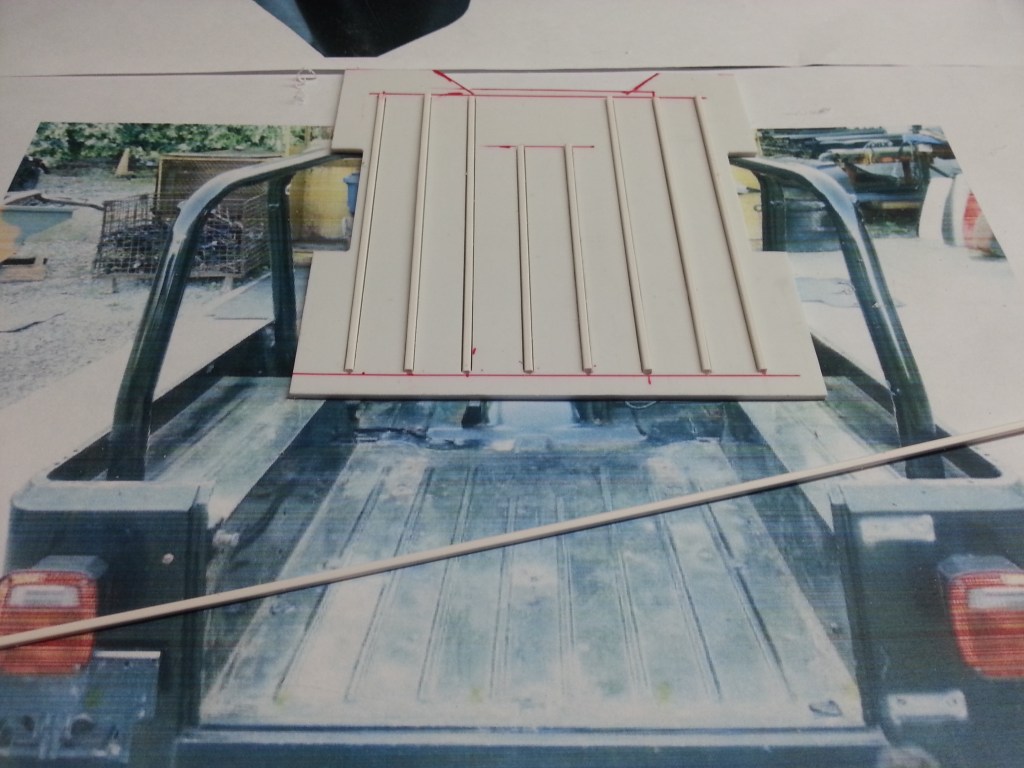
Die so entstandene Optik wirkt verblüffend realistisch. Ohne Einfräsung hätte die angedeutete Sicke zu weit übergestanden. Ein noch flachere Vierkantleiste habe ich nicht bekommen können. Sie so schmal selbst anzufertigen ist ein schwieriges Unterfangen. Die Arbeit wollte ich mir auch nicht machen.

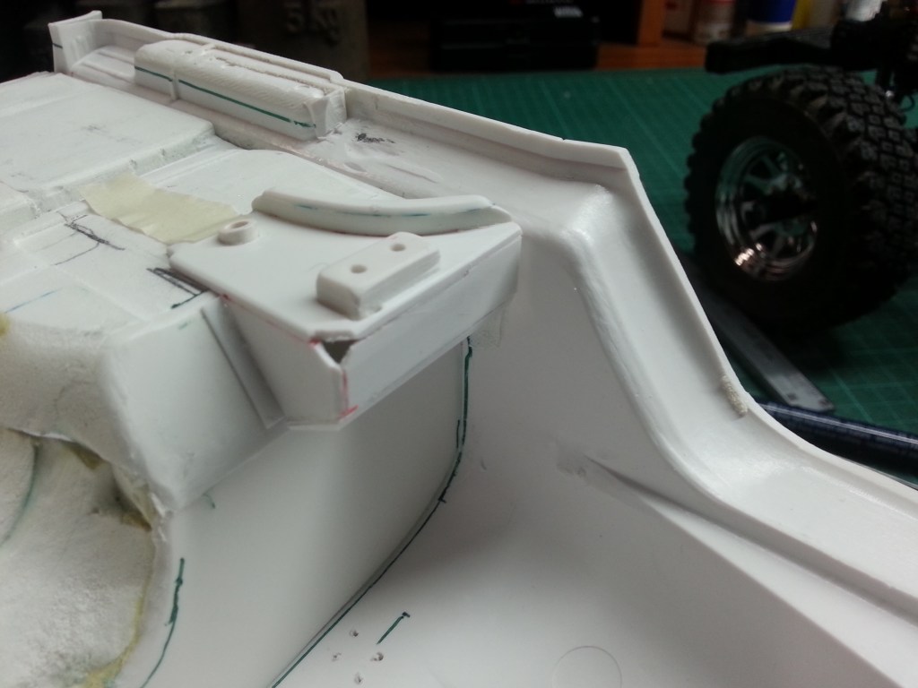
Die im letzten Beitrag begonnene Halterung des Fahrerhauses auf dem Rahmen, wurde fortgesetzt. Insgesamt 18 kleine Bauteile ergaben die Optik, für eine realistische Befestigung.


Für die beiden dazugehörigen Metallhalter am Leiterrahmen, habe ich einen ganzen Nachmittag gesägt, gefeilt, gefräst und gebohrt…
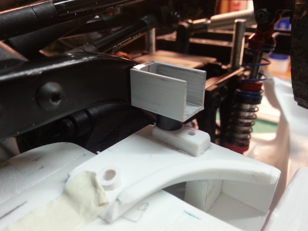
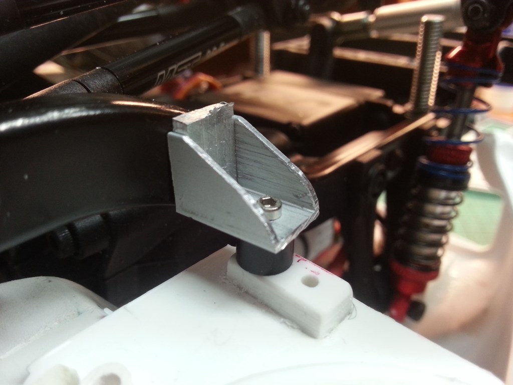
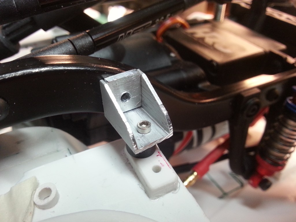
Nach Verklebung der Alu-Teile und zwei Bohrlöchern im Rahmen, war die vordere Befestigung der Bodenplatte auf dem Rahmen geschafft. Hinter den Sitzen gibt es eventuell noch eine zweite Halterung, nach identischer Vorlage.

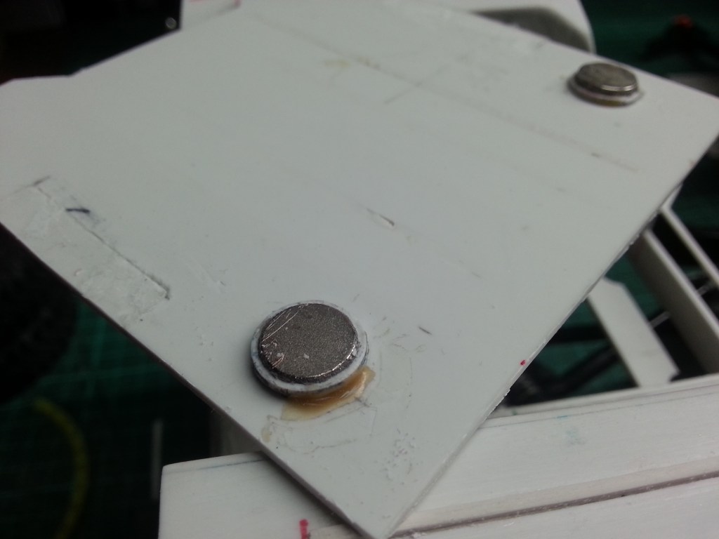
Weitere Magnete sind inzwischen auch eingetroffen. In die Bodenplatte wurden dazu zwei 10 mm Löcher gebohrt, direkt über dem Metallrahmen. Das fixiert die Akku-Fach-Abdeckung auf dem Rahmen. Rechtes Bild
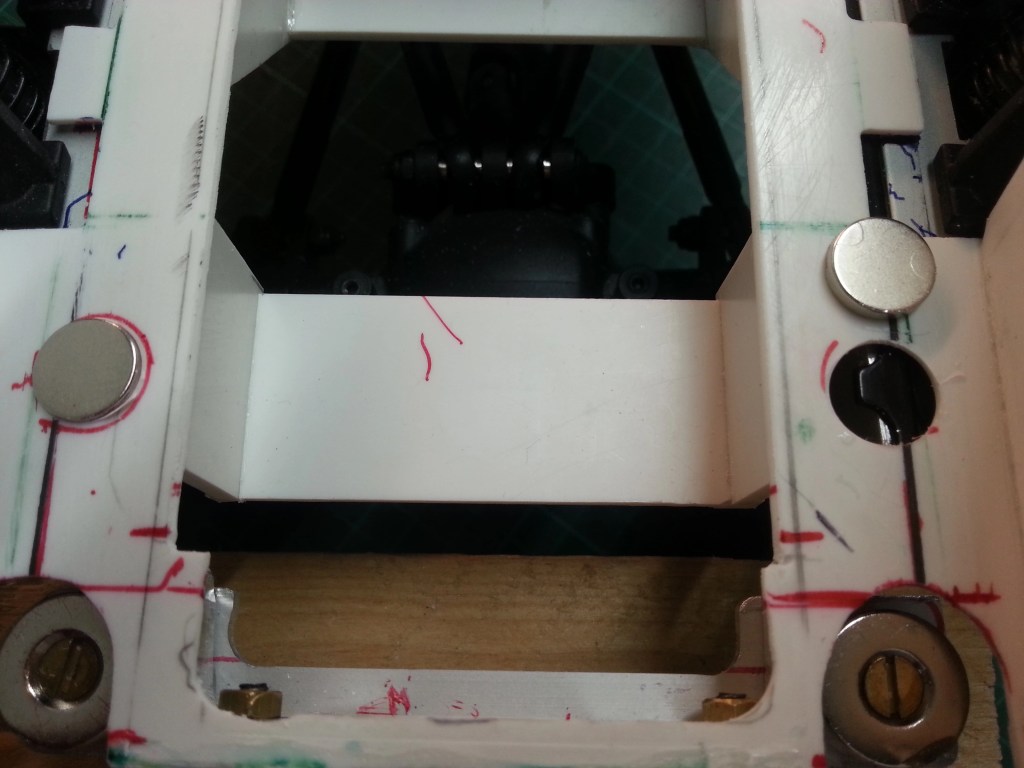
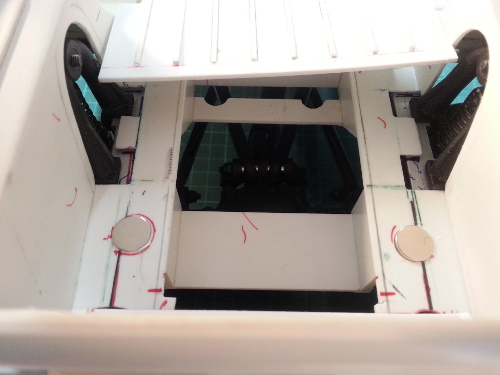
Kleine 1 mm flache Scheiben, abgeschnitten von einem 12 mm Kunststoffstab, dienten als Fixierung für die Magnete. Mit Stabilit Express wurden Scheiben, Magnete und Bodenplatte miteinander verklebt.
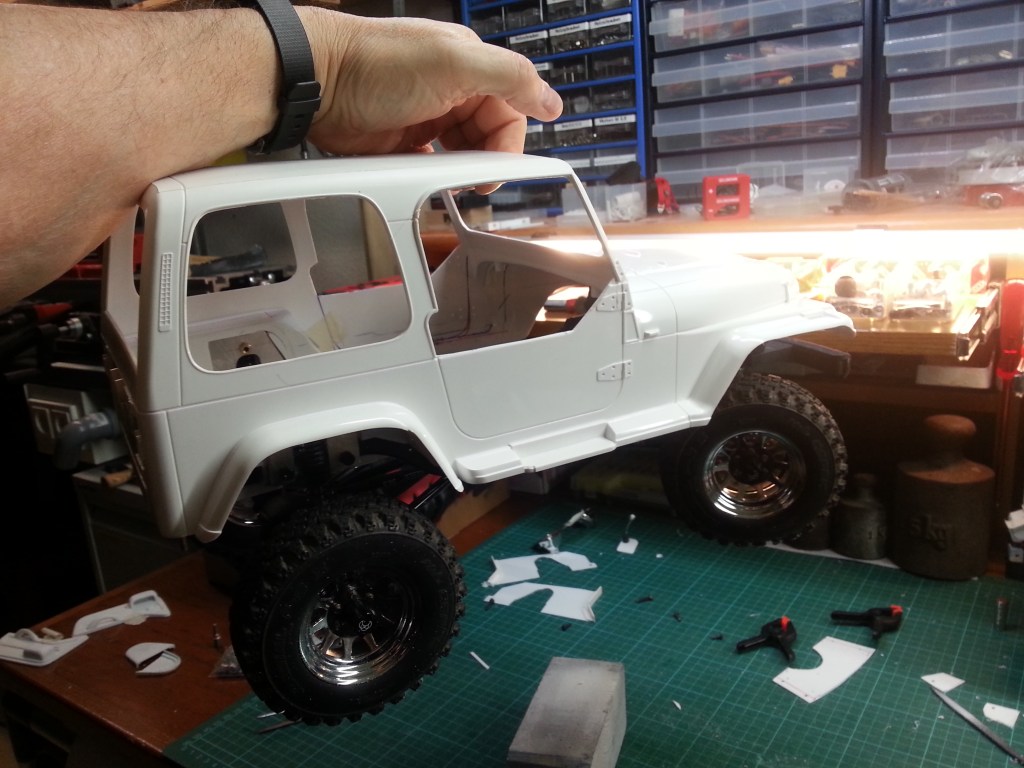
Der restliche Kleber fixierte schließlich noch die beiden vorderen Magnete unter der Motorhaube. Hersteller Pattex gibt an, dass der 2-Kompenentenkleber nach 1 Stunde ausgehärtet sein soll. 3 Stunden habe ich gewartet und das Ergebnis ist perfekt. Das Fahrgestell hängt erstmals vollständig unter der Karosserie, nur von den 4 Magneten gehalten.
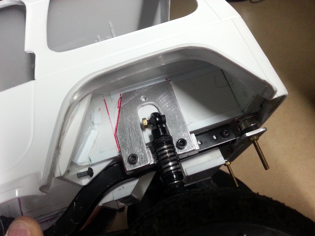
Die hinteren Stoßdämpferaufnahmen kamen noch einmal auf die Werkbank. Das U-Profil war durch die Aussparung für den Stoßdämpfer nicht mehr stabil genug. Alu-Vollmaterial 10×10 mm kam daher zum Einsatz. Bei diesem Umbau habe ich auch gleich die originale Dämpferhalterung neu gebaut. So wurde doch noch ein zukünftiger Wunsch im Nachhinein geschafft. Der Innenraum ist nun endlich nahezu frei von Einbauten. Für die Aussparung der Dämpferhalterung gibt es später auch noch eine Abdeckung. Die zwei Schraubenköpfe für die obere Stoßdämpferaufnahme werde ich dafür klaglos hinnehmen. 😉
Der Innenraum erhielt weitere Optimierungen in Form von eingepassten PS-Teilen im Bodenbereich. damit wurden u.a. Unzulänglichkeiten bei der Vorarbeit kaschiert. Unter den Sitzen und im Fußraum wurden auch Blechsicken angebracht. Nachfolgend die Vorher-Nachher-Bilder.

Fertig gekaufte Sportsitze waren vorne geplant, fallen aber sehr schmal aus und es stand die Prüfung an, ob eine beleibte Fahrerfigur darin Platz findet. Ansonsten gibt es eine weitere Baustelle. Also Sitzprobe mit einem sympathischen Typen.

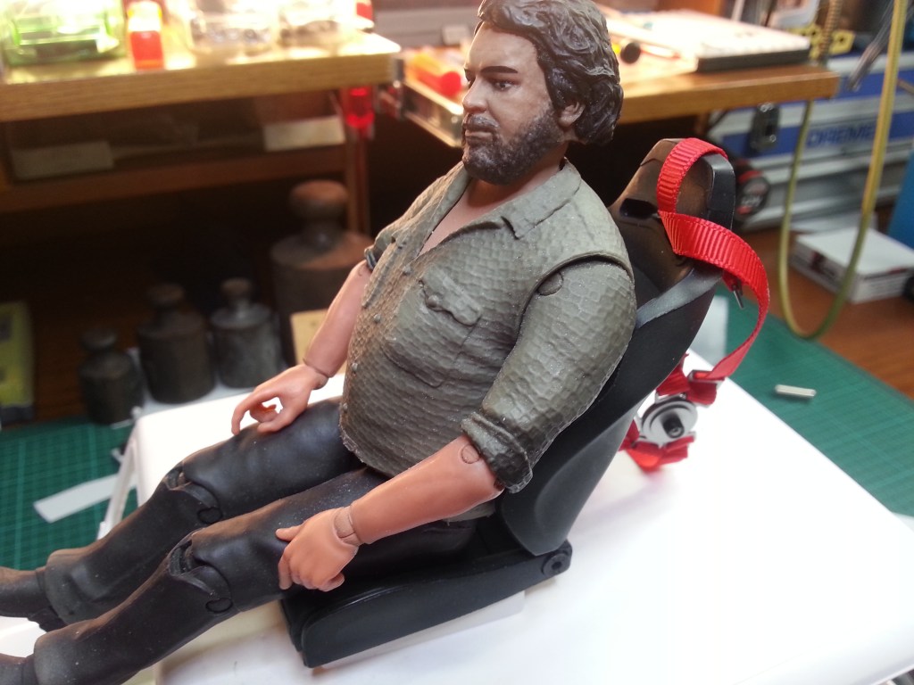
Wie befürchtet, die Sitze sind für diese Figur leider nicht geeignet. 😭
Die Frage ob eine andere Figur oder der Bau eines passenden Sitzes der richtige Weg sind, muss ich jetzt mit mir ausmachen.
Bitte noch etwas Geduld, wird schnellstmöglich fortgesetzt…🙄
English Version
Überschrift
Sources: Internet image search, Pattex glue
Again, nothing written for a long time. My private house construction site currently keeps me completely away from model building. Nevertheless, some things have been built after Christmas. But I would like to present it.
So here is the progress made so far in building my Wrangler. I started with the further design of the cargo area. According to the prototype, the floor and the upper sides of the fenders should get a structure. According to the pictures, the number of sheet metal beads was drawn on the surfaces in even distances. With a milling cutter on the coordinate table grooves were milled and PS strips 1.5 x 1.5 mm were glued into them.
The resulting look is amazingly realistic. Without milling, the indicated bead would have protruded too far. I could not get an even flatter square strip. To make it so narrow by myself is a difficult task. I didn’t want to do the work myself either.
The mounting of the cab on the frame, started in the last post, was continued. A total of 18 small parts gave the optics, for a realistic mounting.
For the two associated metal holders on the ladder frame, I sawed a whole afternoon, filed, milled and drilled …
After gluing the aluminum parts and drilling two holes in the frame, the front attachment of the floor plate to the frame was done. Behind the seats there might be a second mount, following the identical pattern.
More magnets have arrived in the meantime. Two 10 mm holes were drilled into the floor plate, directly above the metal frame. This fixes the battery compartment cover to the frame. Right picture
Small 1 mm flat discs, cut from a 12 mm plastic rod, served as fixation for the magnets. Disks, magnets and base plate were glued together with Stabilit Express.
The remaining glue finally fixed the two front magnets under the hood. Manufacturer Pattex states that the 2-component adhesive should be cured after 1 hour. I waited 3 hours and the result is perfect. The chassis hangs completely under the body for the first time, held only by the 4 magnets.
The rear shock absorber mounts went to the workbench once again. The U-profile was no longer stable enough due to the recess for the shock absorber. Therefore I used aluminum solid material 10×10 mm. During this modification I also rebuilt the original shock mount. Thus a future wish was still created afterwards. The interior is now finally almost free of internals. For the recess of the damper mount there will be a cover later. The two screw heads for the upper shock absorber mount I will accept for this without complaint 😉.
The interior received further optimizations in the form of fitted PS parts in the floor area. thus, among other things, shortcomings in the preliminary work were concealed. Sheet metal beading was also added under the seats and in the footwell. Below are the before and after pictures.

Ready-bought sports seats were planned for the front, but they turn out very narrow and a test was pending to see if a corpulent driver figure could fit in them. Otherwise there is another construction site. So seat test with a sympathetic guy.
As feared, the seats are unfortunately not suitable for this figure. 😭
The question of whether another figure or the construction of a suitable seat are the right way, I must now make out with myself.
Please still a little patience, will continue as soon as possible …🙄
Translation, with the kind support of deepl.com
