Quellen: Magnethandel
English Version
Um diffizile Bauteile herzustellen, verwende ich gerne Papier. Daraus lassen sich auch komplizierte Bauteile fertigen und das reduziert letztlich den Verschnitt von Kunststoffplatten. Nach dieser Strategie entstanden nachfolgend, die unteren beiden Teile.
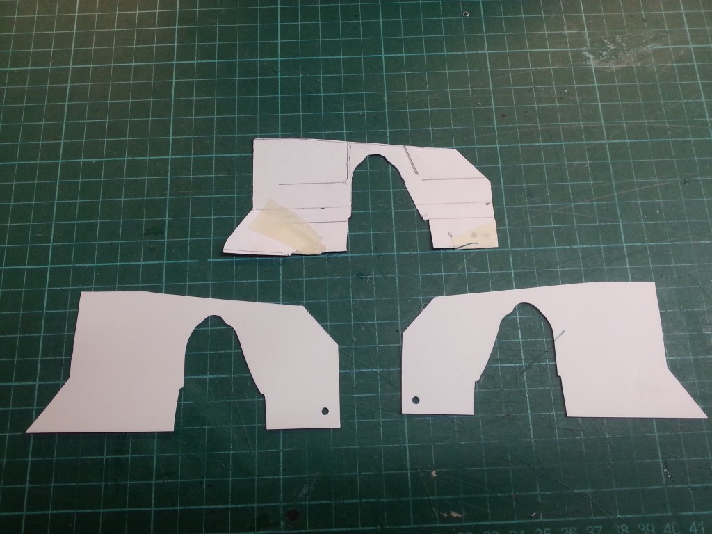
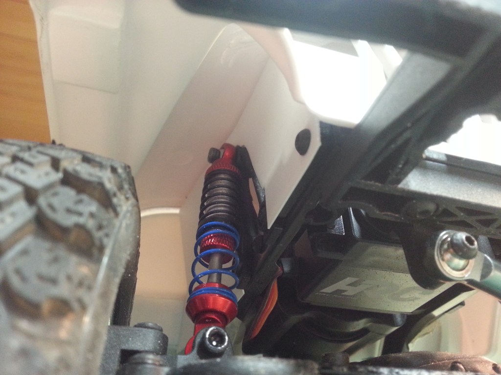
Die seitlichen Abschlüsse zum Motorraum. Für die Papier-Vorlage oben habe ich fast zwei Stunden gebraucht. Zuerst eine grobe Form um die Stoßdämpferaufnahme schneiden. Danach den Rest bis zum Heck, die finale Höhe und natürlich das fehlende Teil bis zum Kühler. Aus den drei Teilen entstand das Hauptteil, wie oben zu sehen. Als Abschluss wurde noch ein kleines Teil für den nachvorne geneigten Fußraum ausgeschnitten und angeklebt. Hier werde ich aber sicher noch einmal nacharbeiten müssen.
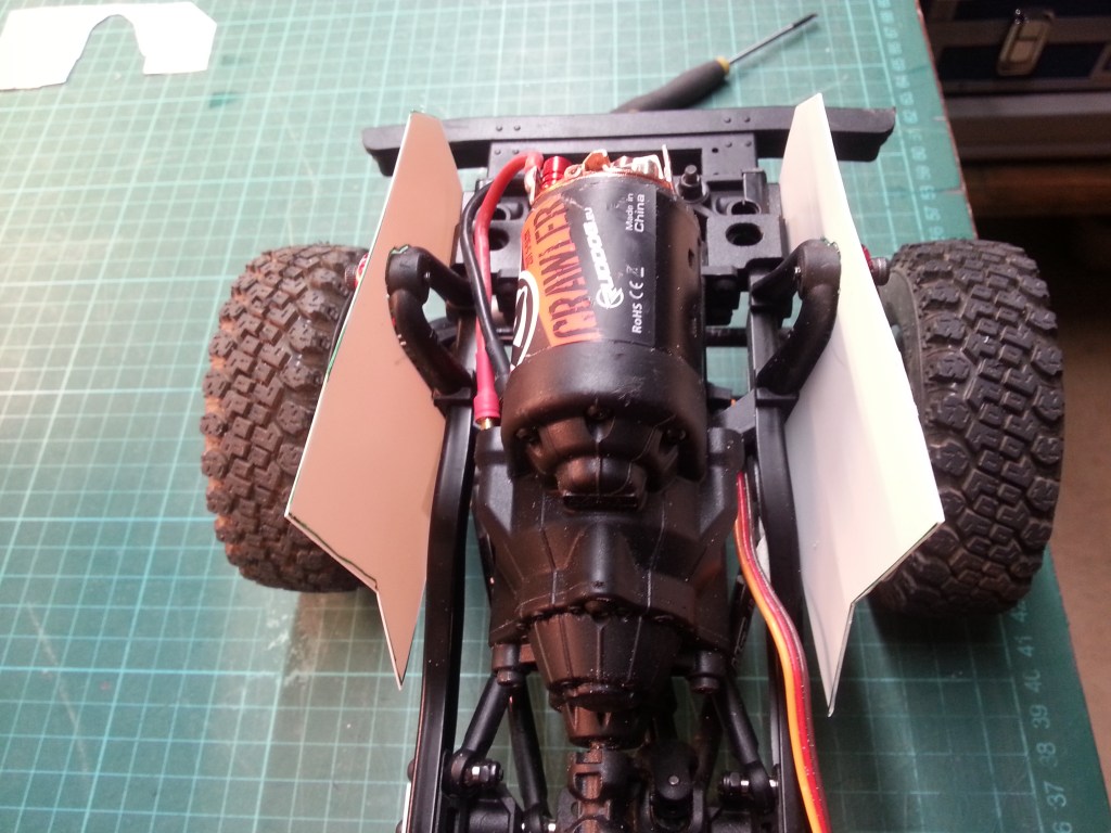
Nachdem die Karosserie endlich ihren Platz und Höhenlage gefunden hatte, musste zuerst der spätere Standort für Empfänger und Fahrtregler gebaut werden. Das wäre in diesem Fall der Motorraum. Ist der Vorderwagen stabilisiert, kann auch der Heckbereich fixiert werden. Um die sehr dünnen Seitenteile aus 0,5 mm PS-Platten etwas widerstandsfähiger zu bekommen, habe ich noch eine Rückwand aus einer 1,0 mm PS-Platte gebaut, wieder durch eine Vorlage aus Papier.
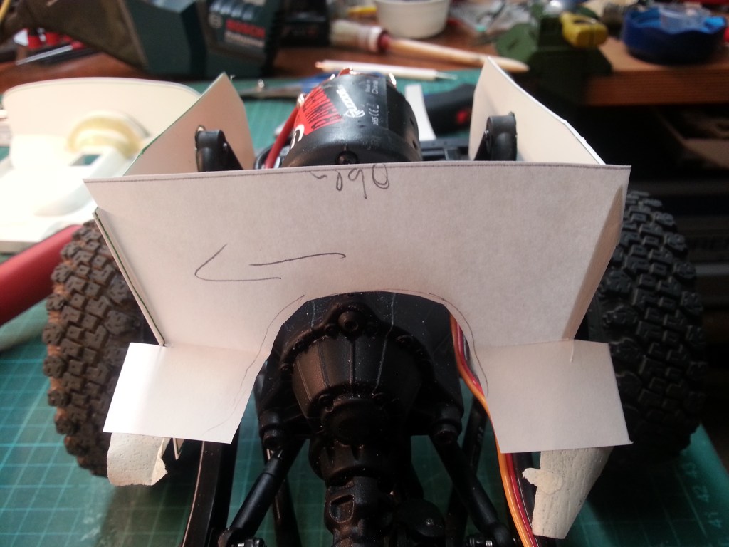
Durch übertragen auf PS, die fertige Rückseite und alles erst einmal mit Malerkrepp provisorisch verklebt. So lässt sich nachträglich immer noch etwas verändern.
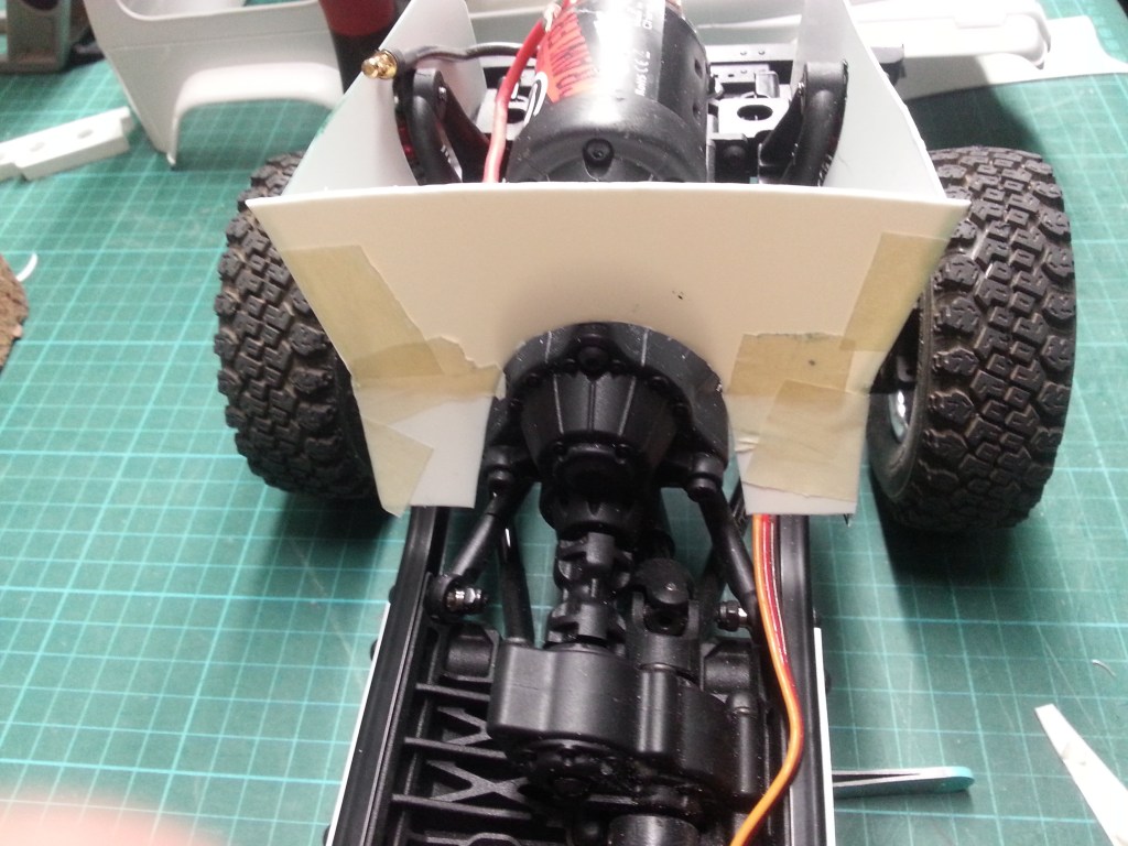
Jetzt der ultimative Test, mit dem in der Karosserie befestigten Bodenaufbau.
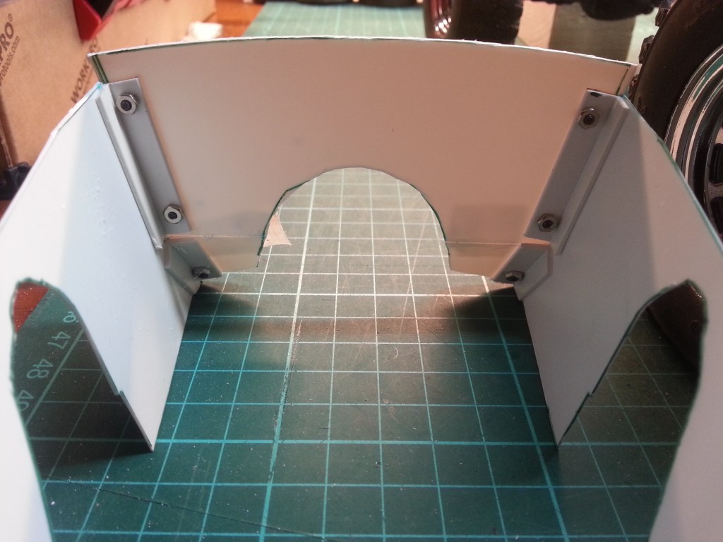
Dieses Mal hatte alles gepasst und Winkelleisten auf der Innenseite des Motorraums, fixieren Feuerwand und Seitenteile miteinander. Immerhin soll daran die Steuerelektronik ihren Platz finden. Das sind zwar keine Schwergewichte, aber bei einem Überschlag oder seitlichen Roller, erzeugen auch sie eine dynamische Masse. Bisher sind nur vorne, im Bereich der Stoßstange, zwei Befestigungsschrauben für die Konstruktion vorhanden. Mindestens eine weitere Befestigung werden ich aber noch bauen.
Als vorderer Abschluss wurde aber zuerst eine Kühlerattrappe gebaut. Das fing so an; eine zwischen die Seitenteile eingepasste Forex-Platte, erhielt einige Bohrungen und Ausfräsungen. Auch auf der nicht sichtbaren Rückseite, wurde zur Gewichtsoptimierung ein Fenster ausgefräst.
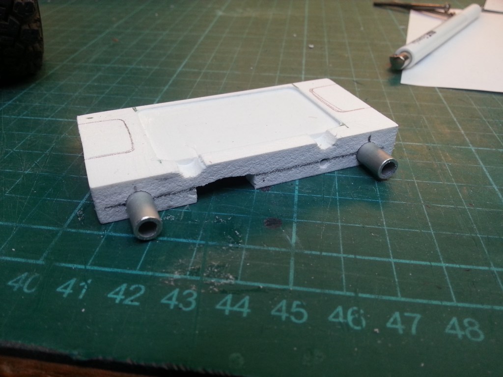
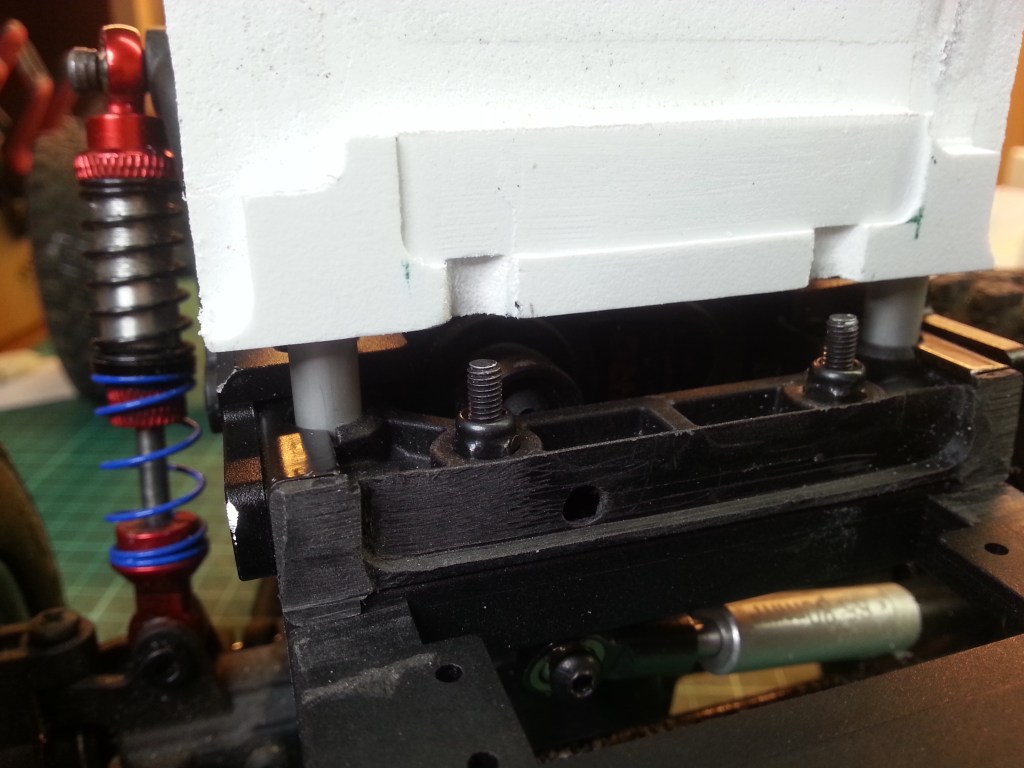
Auf der Unterseite stecken die 6 mm Aluminiumrohre, in entsprechenden Bohrungen der Rahmentraversen.
In diesem Fall eher zufällig, beim realen Modell ist das optisch ähnlich aufgebaut, aber deutlich filigraner.
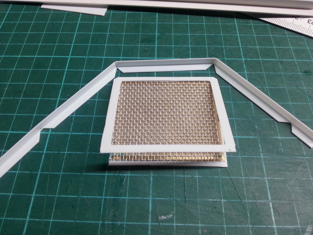
Diese Hilfskonstruktion wird vor den Halteblock montiert und stellt die Kühlerattrappe dar. Eine PS-Platte 0,5 mm, darauf ein Diagonallochblech in Messing, eine Lage Drahtgitter, eingefasst von einem PS-Rahmen und alles gerahmt mit einem PS-Winkel.
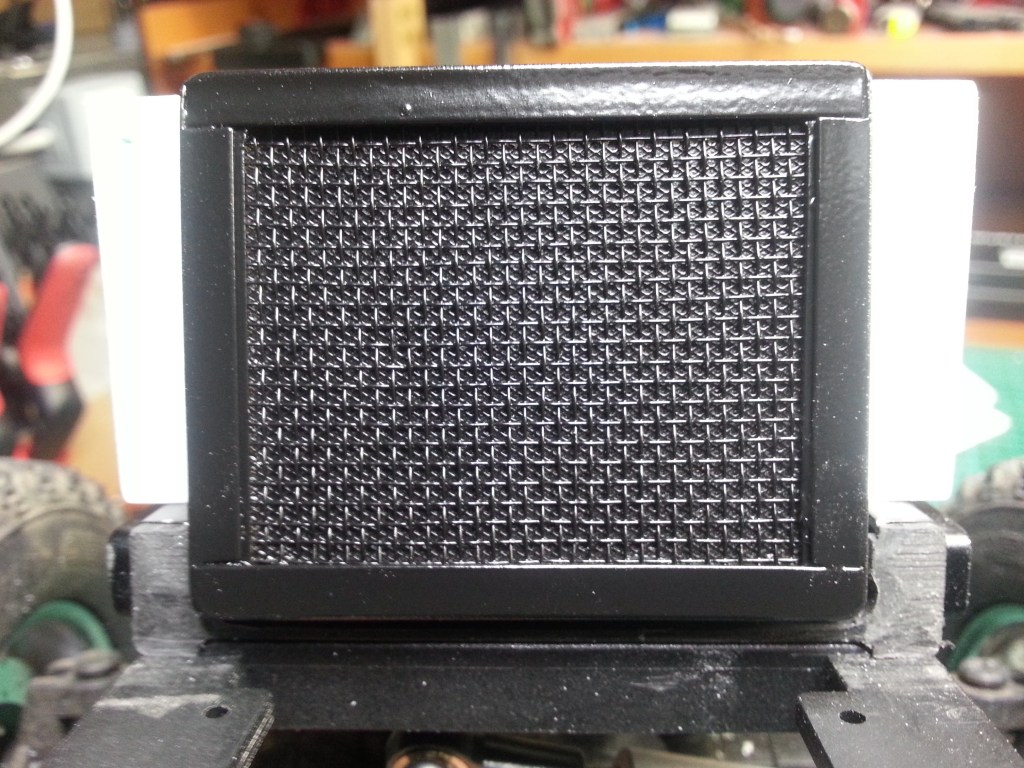
Fertig verklebt und lackiert, sieht es jetzt so aus.
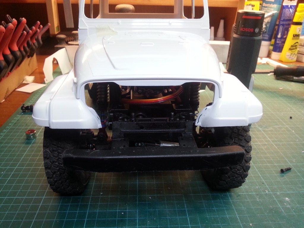
Nachdem nun alles an seinem Platz scheint, wichtige Schnitte an der Front. Die Originalmaske des Bausatzes ist ohnehin wenig aufregend und der ursprüngliche Besitzer hatte schon einige Anbauten entfernt. Jetzt habe ich noch einige Schnitte dazugefügt. Zuerst also das alte Gesicht verloren…
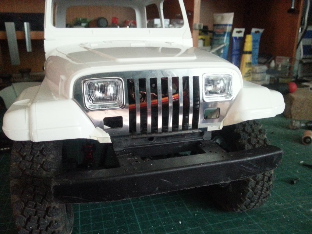
… um schließlich ein Neues zu bekommen. Nicht ganz ohne Nacharbeit. Der Knick unterhalb der Scheinwerfer, wollte sich nicht ohne weiteres an die Karosserieform anschmiegen. Mit etwas Nachdruck, ließ sich der Kühlergrill aber in seine neue Form bringen. Unabhängig von der ansprechenderen Optik, sind so auch Aufnahmen für funktionsfähige Blinker vorhanden.
Eine kurze Erläuterung vorab, zur Befestigung der Karosserie. Neodym-Magnete, als Süd– oder Nordpolung definiert, fixieren die Karosserie auf dem Rahmen.
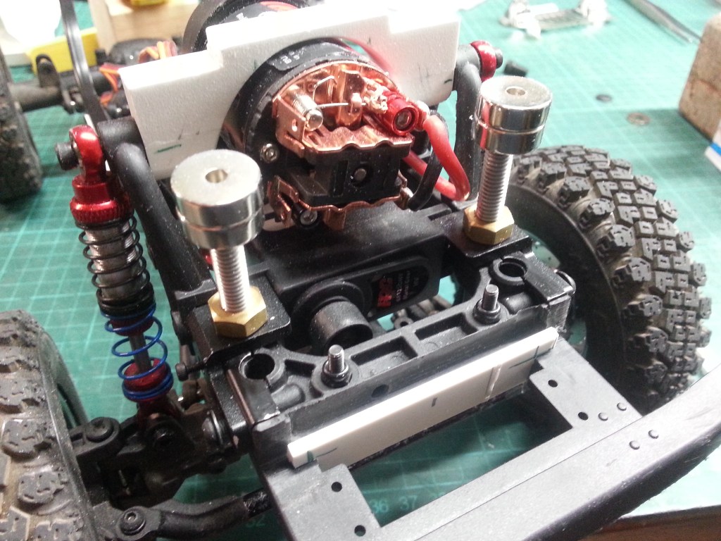
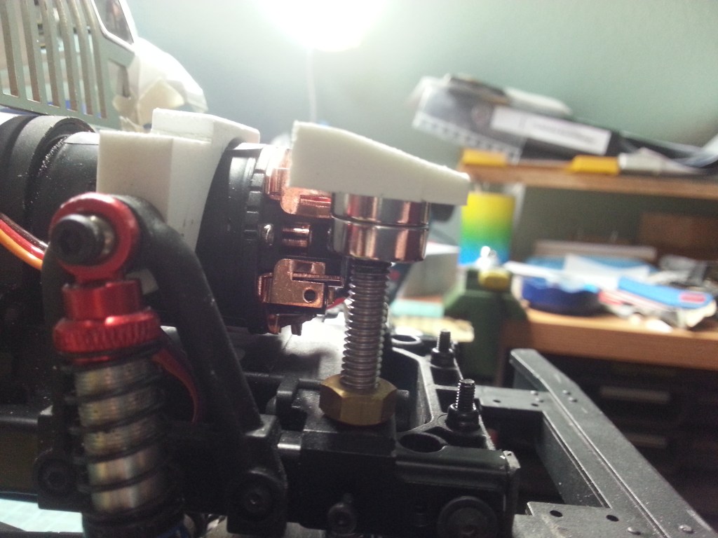
Die vordere Magnetbefestigung; Zwei M6-Gewindestäbe, mit einer 3mm Bohrung und Gewinde versehen, werden als Träger für die Magnete verwendet. So kann ich nachträglich in Grenzen, die Höhe der Karosserie zum Fahrgestell variieren.
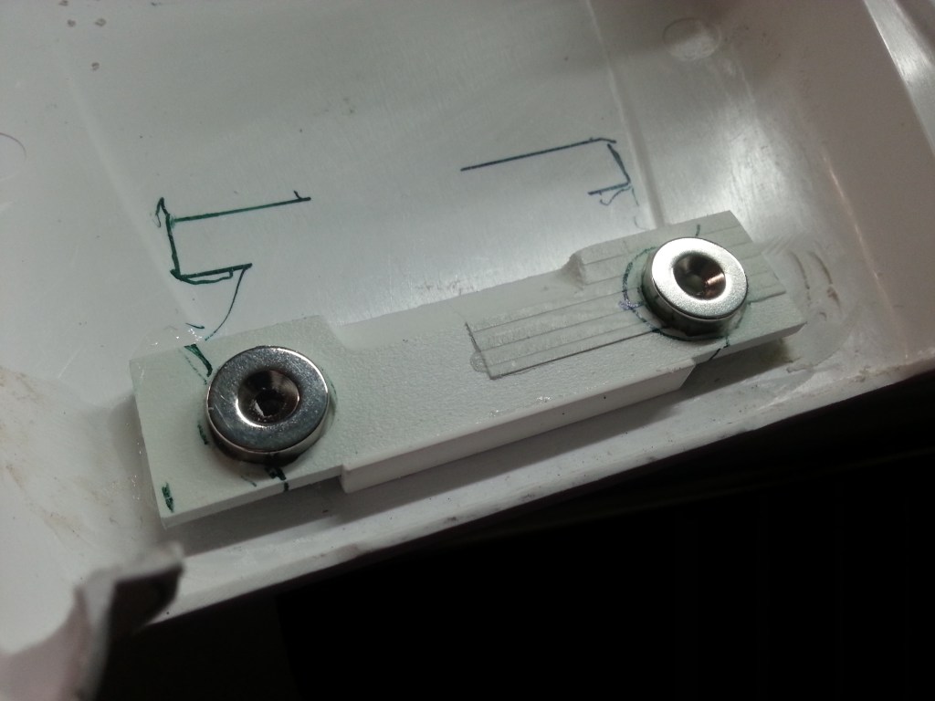
Die Magnete werden nun mit einem an die Karosserieform angepassten Bauteil, jeweils unter der Haube verklebt.
Im nächsten Blogbeitrag soll die hintere Karosseriehalterung, das Heckabteil und die nach außen versetzte Stoßdämpferhalterung entstehen.
Wird schnellstmöglich fortgesetzt…
English Version
Jeep Wrangler YJ, interior and other work
Sources: Magnet Shop
I like to use paper to make complicated components. It can also be used to make complicated components, which ultimately reduces the amount of waste from plastic sheets. The two lower parts were made according to this strategy.
The lateral closures to the engine compartment. It took me almost two hours to make the paper template above. First cut a rough shape around the shock absorber mount. Then the rest up to the rear, the final height and of course the missing part up to the radiator. From these three parts the main part was created, as seen above. Finally, a small part for the forward sloping footwell was cut out and glued on. But I will certainly have to do some more work here.
After the body had finally found its place and height, first the later location for receiver and speed controller had to be built. In this case that would be the engine compartment. Once the front of the car is stabilised, the rear can also be fixed. In order to make the very thin side parts made of 0.5 mm PS boards a bit more resistant, I built another rear wall out of a 1.0 mm PS board, again by using a template made of paper.
By transferring it to PS, the finished back and gluing everything with masking tape for the time being. This way you can always change something afterwards.
Now the ultimate test, with the floor structure fixed in the body.
This time, everything fitted and angled strips on the inside of the engine compartment fix the firewall and side panels together. After all, the control electronics are supposed to find their place there. These are not heavyweights, but in the event of a rollover or sideways roll, they too generate a dynamic mass. So far, there are only two fastening screws for the construction at the front, in the area of the bumper. But I will build at least one more fastening.
But first, a dummy radiator was built as the front end. It started like this; a forex plate fitted between the side panels was drilled and milled out. A window was also milled out on the rear side, which is not visible, to optimise the weight.
On the underside, the 6 mm aluminium tubes are inserted in the corresponding holes in the frame cross members.
In this case it is rather coincidental, but on the real model it is visually similar, but much more filigree. This auxiliary construction is mounted in front of the holding block and represents the dummy cooler.
A PS plate 0.5 mm, a diagonal perforated brass plate on top, a layer of wire mesh, framed by a PS frame and everything framed with a PS angle.
Finished glued and painted, it now looks like this.
Now that everything seems in place, important cuts to the front. The original mask of the kit is not very exciting anyway and the original owner had already removed some attachments. Now I have added some cuts to it. So first the old face lost…
… to finally get a new one. Not without some rework. The bend below the headlights, it didn’t want to fit easily to the body shape. But with a bit of pressure, the radiator grille could be brought into its new shape. Independently of the more appealing appearance, the grille now also has a place for functional turn signals.
A short explanation in advance, about the attachment of the body. Neodymium magnets, defined as south or north poles, fix the body to the frame.
The front magnet fastening; two M6 threaded rods, with a 3mm hole and thread, are used as supports for the magnets. This way I can vary the height of the body to the chassis within limits.
The magnets are now glued under the bonnet with a component adapted to the shape of the body.
In the next blog post, the rear body mount, the rear compartment and the outwardly offset shock absorber mount will be created.
Will be continued as soon as possible…
Translation, with the kind support of deepl.com
