Quellen: Internet Bildersuche
English Version
Es ist erstaunlich, wie viel Zeit ich inzwischen am Koordinatentisch verbringe. Die Bodengruppe ist aus einer 10 mm dicken Forex-Platte gefräst worden. Eine Menge Kleinteile sind ja inzwischen schon so entstanden, aber die Bodenplatte wahr schon eine besondere Herausforderung. Viele Ebenen und Winkel waren zu erschaffen. Dazu Rundungen, die ich inzwischen fast perfekt, mit den beiden Achsen freihändig realisieren kann. Auch Fehler sind so natürlich entstanden, die ich aber durch weiteres Ausfräsen und Einpassen eines neuen Forex-Teiles, reparieren konnte. Trotz Fixierung auf einem stabilen Unterbau gab es Verspannungen, die zu unterschiedlichen Höhen geführt haben. Auch hier musste durch Aufkleben zusätzlicher PS-Plattenstücken, ein Ausgleich geschaffen werden. Ein Bauteil also aus vielen Einzelteilen. Ein Mann wächst an seinen Aufgaben…😂
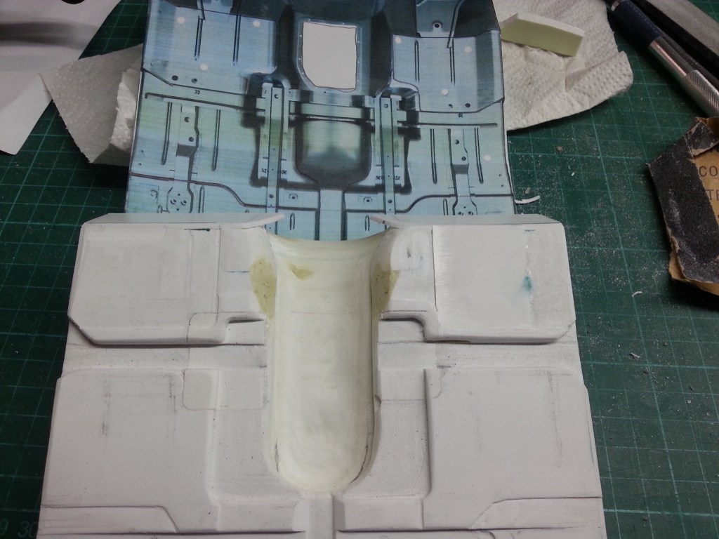
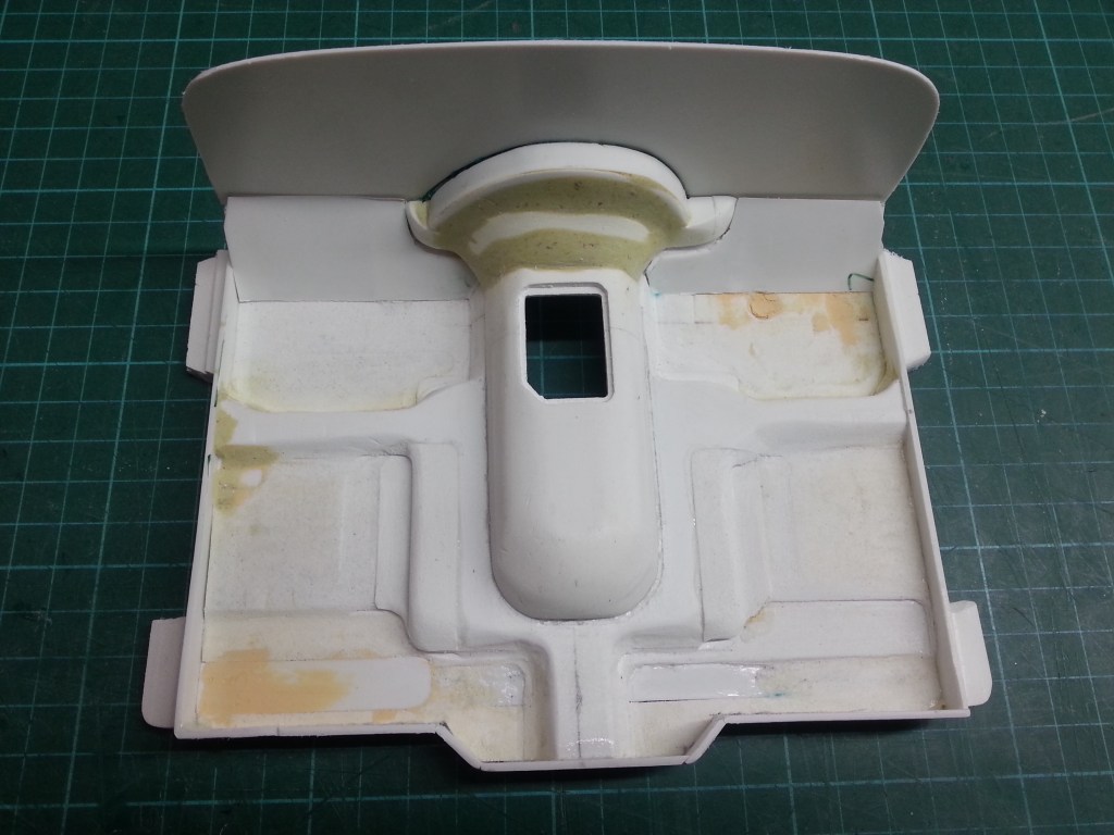
Nachdem also im ersten Teil die Oberseite entstanden ist, nun die Unterseite. Später nicht mehr direkt sichtbar, aber wunderschön anzusehen, wenn es gelingt. Hier der noch unbearbeitete Boden, mit dem bereits ausgeschnittenen Bodenteil im Heck.
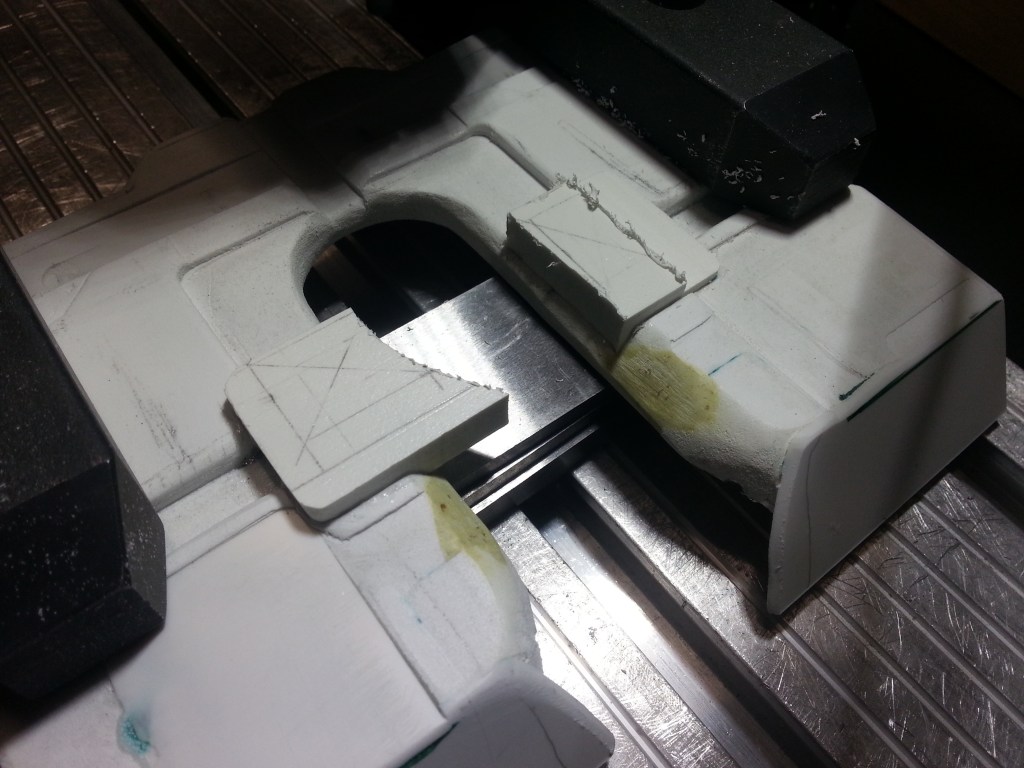
Um die inzwischen vorne nur noch wenige Millimeter starke Bodengruppe nicht weiter zu schwächen und auch den Verzug beim Aufspannen zu verringern, gab es eine vordere Stabilisierung. Der vordere Abschluss zum Fußraum wurde daher zunächst schräg abgefräst…
…eine Kunststoffplatte aufgeklebt und grob an die vorhandene Struktur angepasst. Die Feuerwand und der Kardantunnel, versteifen den vorderen Bereich später endgültig.
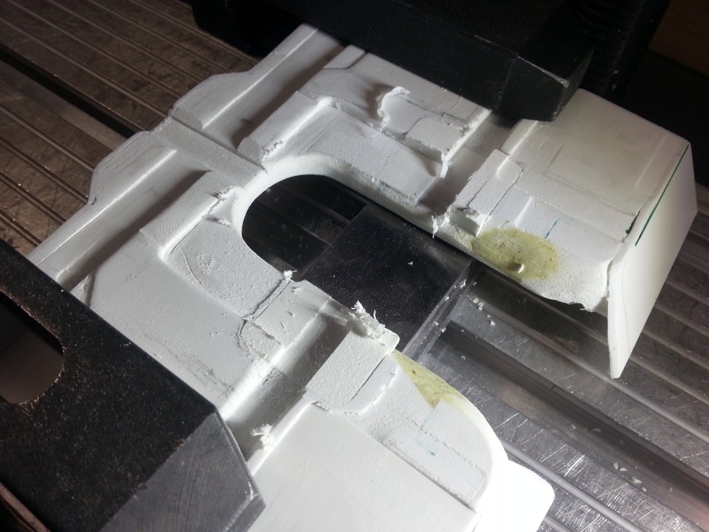
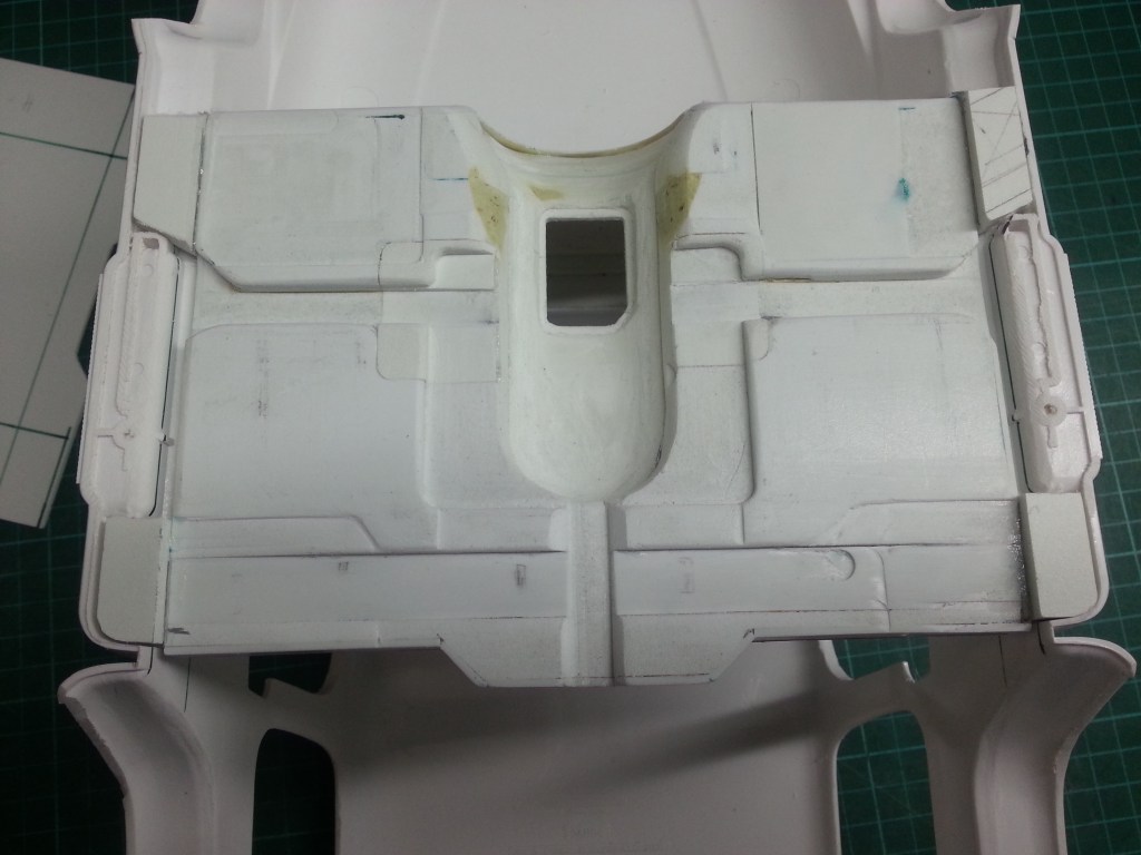
Nach einigen Stunden Fräsen, ein erster Blick auf die spätere Unterseite. Ein weiterer Fehler beim Fräsen, in der Mitte, ist hier noch nicht komplett korrigiert. Dafür vorne rechts schon ein Verstärkungsplatte eingeklebt. Hier hatte sich der Kardantunnel unter dem Druck der Einspannung gehoben und dabei ist leider eine unerwünschte Vertiefung entstanden. Im unteren Bildbereich muss noch eine Ebene abgefräst werden und ebenso die Korrektur im Zentrum des Kardantunnels. Hier werden später die Sitze befestigt.
Nachfolgend, rechts unten die Originalansicht.

Diese Reparatur stelle ich hier einmal beispielhaft im Detail vor. Zunächst wurde die gesamte Fläche ausgefräst, zwei Reparaturstücke angefertigt und verklebt.
Schrittweise wurden die überstehenden Stellen auf das neue Niveau und Kontur abgefräst.
Zurück bleiben nur noch die schwach erkennbaren Übergänge, die aber nach der Feinarbeit mit Spachtel und Farbe verschwinden werden.
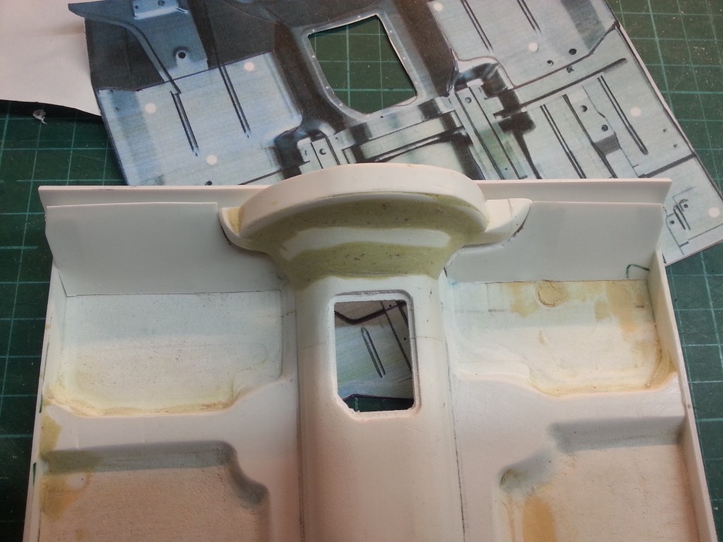
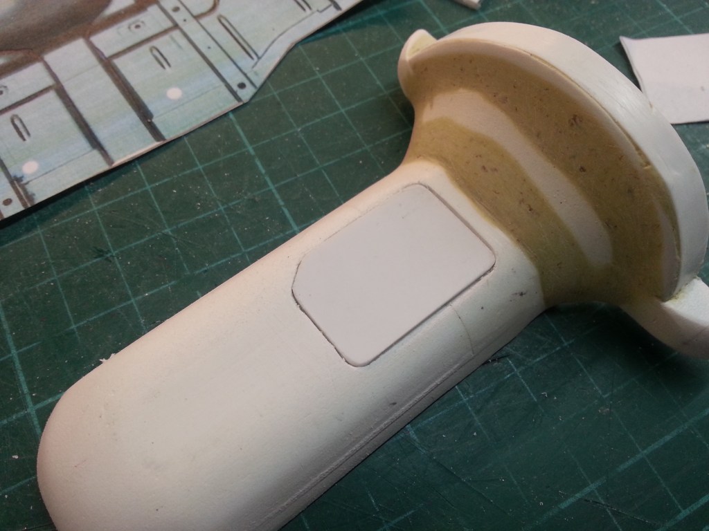
Für den Einbau des Schalt- und Differential-Sperrhebels, wurde die Aussparung in das Kardangehäuse gefräst. Die Abdeckung dafür auch gleich angefertigt.
Analog zur Unterseite musste auch die Oberseite noch einmal modifiziert werden. Ausfräsen, ein passendes Gegenstück anfertigen und verkleben. Nach dem Fräsen, dann das finale Ergebnis.
Der gesamte Kardantunnel ist inzwischen mit dem Unterboden verklebt. Eine Fahrradspeiche, ein in der Bohrmaschine gefertigter Schaltknauf und der gekürzte Faltenbalg einer Fahrrad-V-Brake, ergaben das erstes Equipment im Innenraum; den Schalthebel. Links davon, wird es noch den Umschalthebel für die Zuschaltung des Allradantriebes und der Differentialsperre geben. Einen Handbremshebel im Wortsinn, scheint es im YJ nicht zu geben. Auf allen Fotos fand ich nur einen mittels Fuß betätigten Hebel, vorne links im Fußraum. Ein darüber angeordneter Hebel entriegelt dann wohl die Bremse. Schade, dann muss der bereits anfertigte Handbremshebel wohl in ein anderes Auto.
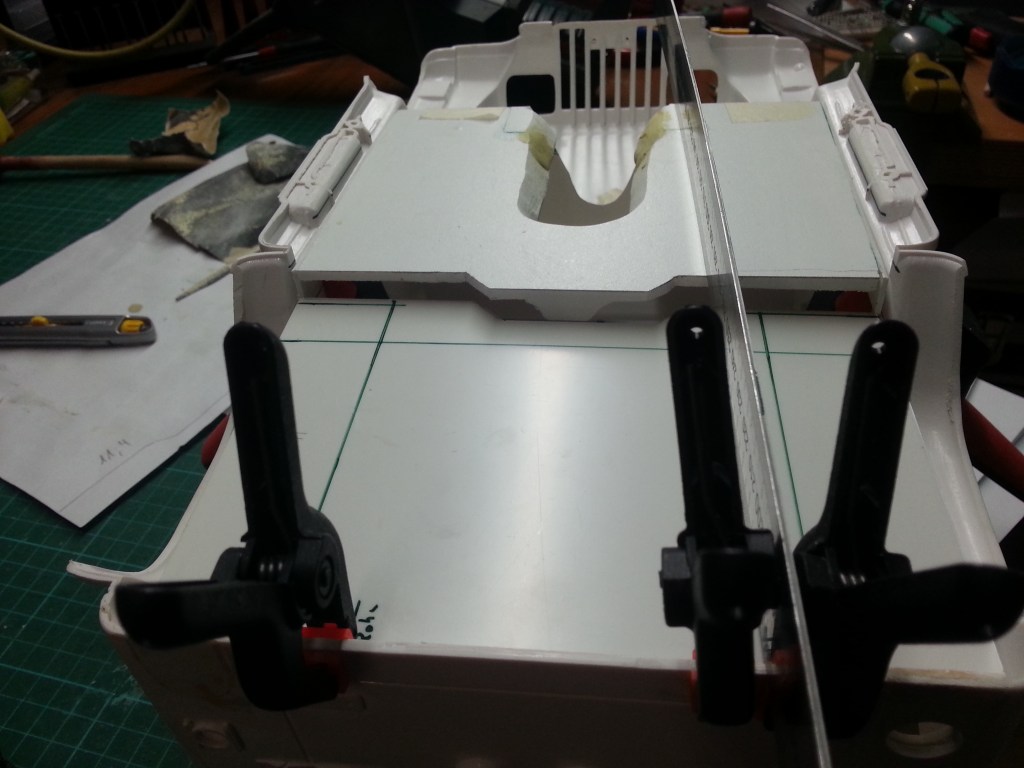
Um weitere Maße für den Innenraumausbau ermitteln zu können, habe ich vier Befestigungspunkte zwischen Bodengruppe und Karosserie gebaut. Verklebt mit der Bodengruppe, liegen ihre Ausleger in den seitlichen Trittbrettern. So ist die spätere Bodenhöhe endgültig definiert und gleichzeitig besteht nun eine formschlüssige Verbindung zur Karosserie.
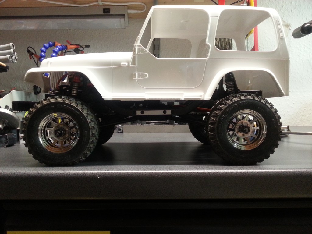
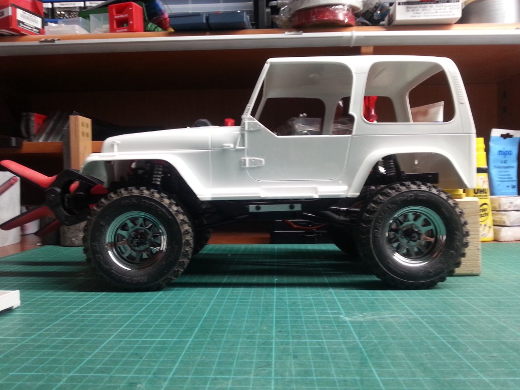
Viel gemessen und probiert, doch es hatte zunächst nicht gepasst. Die Karosserie 3 mm zu weit hinten und die Bodengruppe 3 mm zu weit vorne. Kleine Maße aber eine große Wirkung. Das Hinterrad nicht perfekt im Radkasten zentriert und vorne liegt das Kardangehäuse auf dem Getriebe auf. Weiteres Ausschleifen der oberen Rundung hatte zwar eine Verbesserung gebracht, aber auch die Bodengruppe musste verschoben werden. Das bedeutete wieder schleifen, anpassen, messen. Solange bis alles wunschgemäß passte. Was sind nach der Arbeit schon drei Stunde mehr oder weniger, aber die Karosserie sitzt so einfach noch zu hoch. Mein Versuch die Oberkante der Bodengruppe auf das echte Niveau zu bringen, muss ich bei meiner Bauweise als gescheitert betrachten. Mit der Konsequenz, dass die Nasen abgefräst und an einer veränderten Position neu angebracht werden müssen. Links das vorläufige Ergebnis, rechts das Ziel. Wunsch und Wirklichkeit liegen bisweilen weiter auseinander, als man es sich erträumt.
Wird schnellstmöglich fortgesetzt…
English Version
Jeep Wrangler, Floor Assembly in Detail
Sources: Internet image search
It’s amazing how much time I now spend at the coordinating table. The base assembly was milled from a 10 mm thick forex plate. A lot of small parts have already been made this way, but the floor plate was a special challenge. Many levels and angles had to be created. In addition, curves that I can now realise almost perfectly freehand with the two axes. Of course, there were also mistakes, but I was able to repair them by further milling and fitting a new forex part. Despite being fixed to a stable base, there were tensions that led to different heights. Here, too, compensation had to be achieved by gluing on additional pieces of PS plate. A component made of many individual parts. You grow with your tasks…😂
After the upper side was created in the first part, now the lower side. Later no longer directly visible, but beautiful to look at when it succeeds. Here the still unfinished bottom, with the bottom part already cut out in the rear.
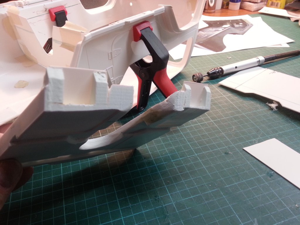
In order not to further weaken the floor assembly, which is now only a few millimetres thick at the front, and also to reduce distortion when stretching, there was a front stabilisation. The front end to the footwell was therefore first milled off at an angle…
…a plastic plate was glued on and roughly adapted to the existing structure. The Partition wall to the engine and the cardan tunnel will later stiffen the front area.
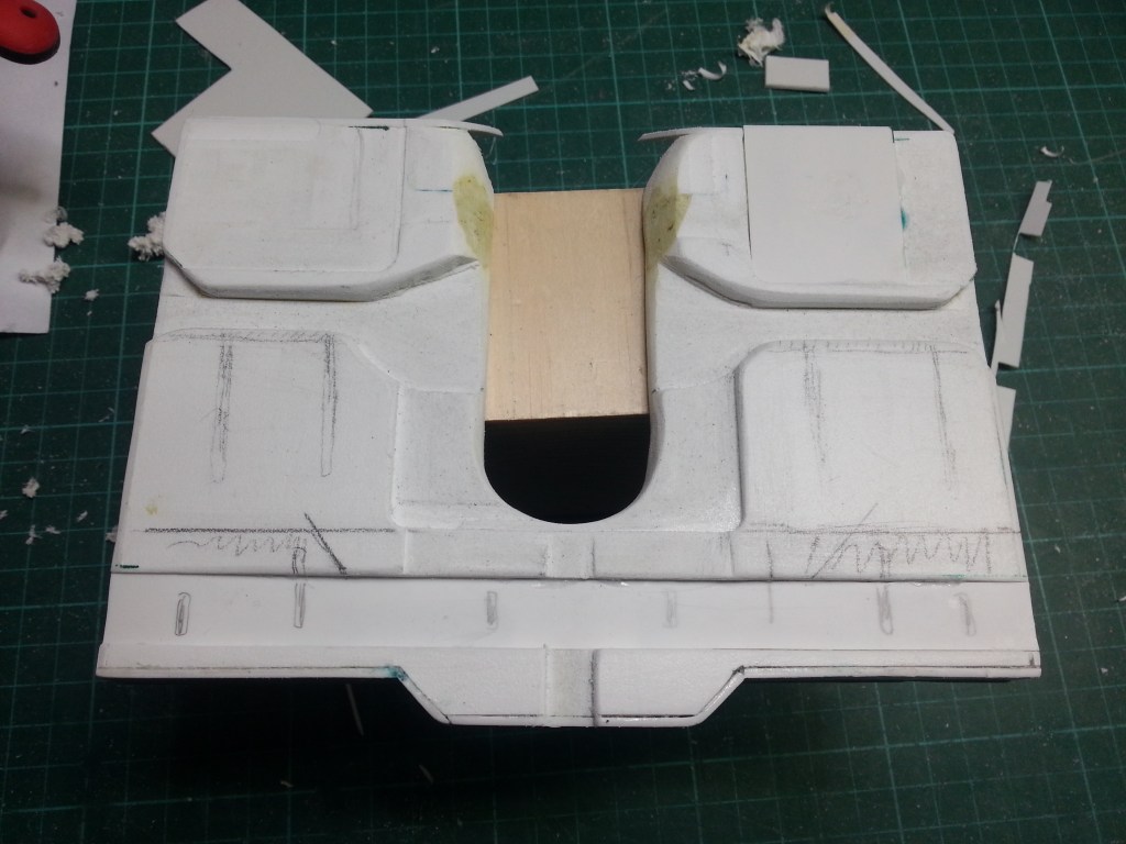
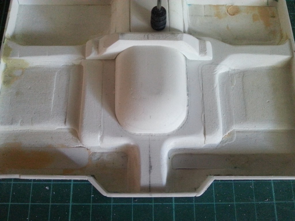
After a few hours of milling, a first look at the future underside. Another mistake made during milling, in the middle, has not yet been completely corrected. Instead, a reinforcement plate has already been glued in at the front right. Here the cardan tunnel had lifted under the pressure of the clamping and unfortunately an unwanted indentation was created. In the lower part of the picture a plane has to be milled off and also the correction in the centre of the cardan tunnel. This is where the seats will be attached later.
Below, on the right, the original view.
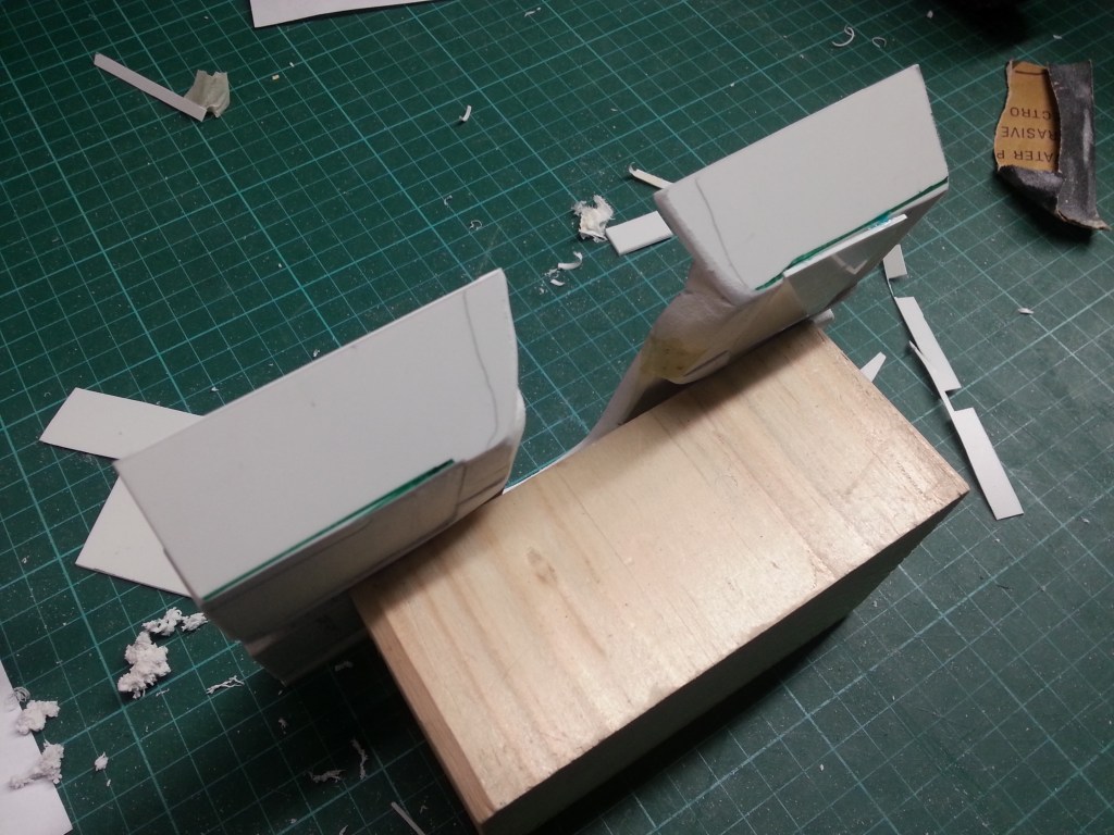
Here I present this repair in detail as an example. First, the entire surface was milled out, two repair pieces were made and glued.
Step by step the protruding parts were milled to the new level and contour.
Only the faintly visible transitions remain, but they will disappear after the finishing work with filler and paint.
For the installation of the gearshift and differential lock lever, the recess was milled into the cardan housing. The cover for it was also made at the same time.
Analogous to the bottom side, the top side also had to be modified. Milling out, making a matching counterpart and gluing it in place. After milling, the final result.
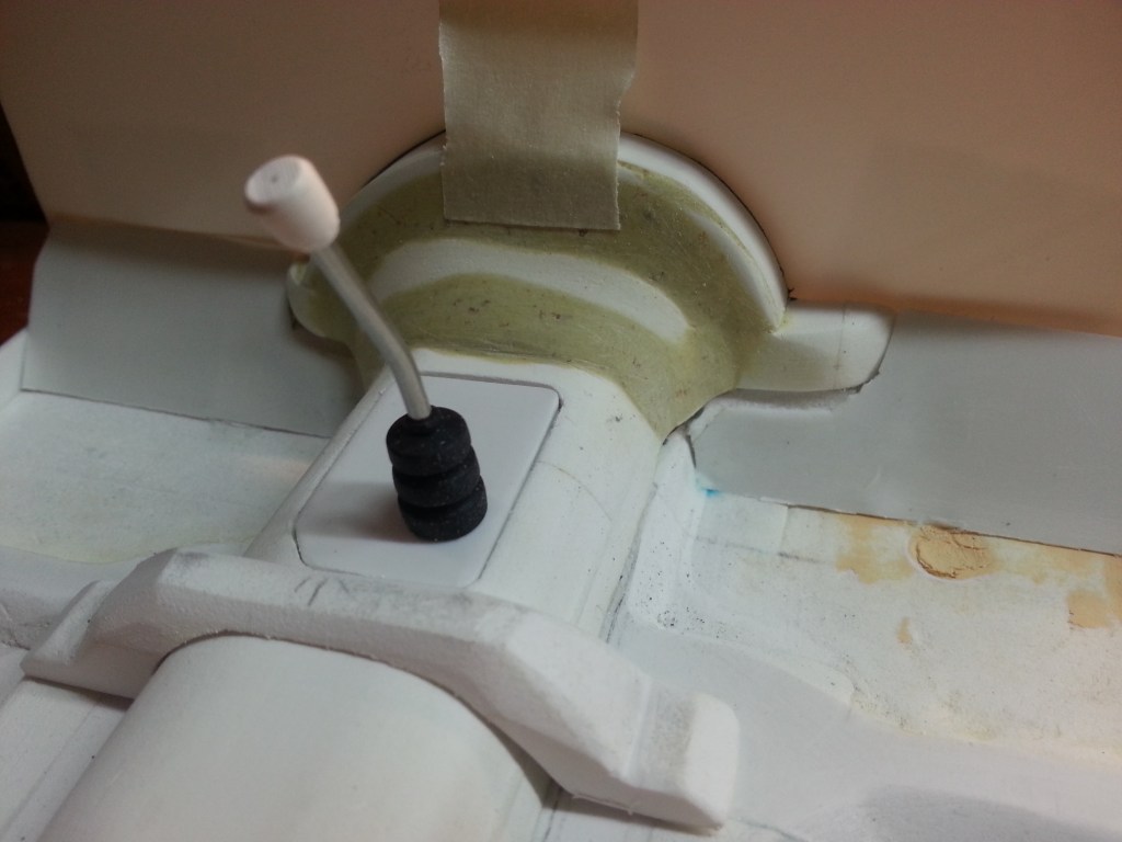
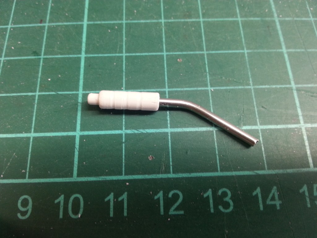
The entire cardan tunnel is now glued to the underbody. A bicycle spoke, a gearstick knob made in the drill and the shortened bellows of a bicycle V-brake resulted in the first equipment in the interior; the gearstick lever. To the left of it, there will also be the shift lever for engaging the four-wheel drive and the differential lock. There doesn’t seem to be a handbrake lever in the literal sense in the YJ. In all the photos I found only a foot-operated lever in the front left footwell. A lever located above it unlocks the brake. Too bad, then the already made handbrake lever will probably have to go in another car.
In order to be able to determine further dimensions for the interior conversion, I built four attachment points between the floor panel and the body. Glued to the floor assembly, their outriggers lie in the side running boards. So the floor height is finally defined and at the same time there is now a form-fit connection to the body.
A lot of measuring and trying, but nothing fit at first. The body was 3 mm too far back and the floor panel 3 mm too far forward. Small measurements but a big effect. The rear wheel was not perfectly centred in the wheel housing and at the front the cardan housing was resting on the gearbox. Further grinding of the upper rounding had brought an improvement, but the floor panel also had to be moved. That meant grinding, adjusting and measuring again. Until everything fit as desired. What are three hours more or less after the work, but the body still sits too high. My attempt to bring the upper edge of the floor assembly to the real level must be considered a failure with my construction method. With the consequence that the lugs have to be milled off again and reattached at a different position. On the left the preliminary result, on the right the goal. Wish and reality are sometimes further apart than one would dream.
Will be continued as soon as possible…
Translation, with the kind support of deepl.com
