Quellen: RC-HP, Internetbildersuche
English Version
In meiner Werkstatt stehen einige Baustellen. Wie und wann ich daran baue, entscheide ich nach Lust und Laune. Der Anlass wieder einmal am Jeep Wrangler zu bauen ist recht banal. RC HP hat die auf Fahrzeuggewicht und Reifengröße angepassten Einlagen geliefert. Ein Service der heute nur noch sehr selten verfügbar ist. Im ersten Bericht zur Fahrerprobung habe ich noch versucht, mit den Original RC4WD-Einlagen zu fahren. Das Ergebnis; zwei Reifen von der Felge abgeschält. Ich hatte aber auch eine Montagehilfe, in Form von Geschirrspülmittel verwendet. Nun die erneute Montage, aber ohne jegliche Hilfsmittel. Eine erste Trockenübung hat die Wirkung der neuen Einlagen absolut bestätigt. Ein Reifen der sich unter Belastung verformt und doch absolut seitenstabil auf der Felge sitzt.
Trockenübung daher, weil ich ja zwischenzeitlich eine weitere Baustelle eröffnet habe, den Ausbau des Innenraums. Der sehr kleine Innenraum des Zweisitzers, lässt kaum Optionen für die Unterbringung von Akku und Elektronik. Zumindest dann nicht, wenn es einigermaßen realistisch zugeht. Alle bisher verbaute Elektronik, musste dazu wieder ausgebaut werden. Bei der Unterbringung des Akkus wird es sehr eng zugehen und ich muss meinen Akku-Fundus um kompaktere Modelle ergänzen.
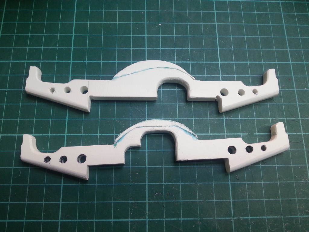
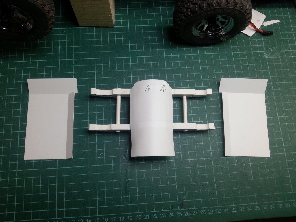
Aber bleiben wir in der Reihenfolge. Da ich plane, die Karosserie von der Bodenplatte trennen zu können, musste eine stabile Trägerkonstruktion gebaut werden. Einmal nicht exakt nach dem Original, da dann eine stabile, aber schwere Bodenplatte nötig wäre, um alles auf dem Rahmen zu halten. Um Gewicht einzusparen, verwende ich nur 0,5 mm starke PS-Platten. Technisch sollte es aber schon aussehen und so habe ich diese beiden Konstruktionen gebaut. Sie sitzen später auf dem Rahmen, verbunden mit zwei PS-Streifen und diese jeweils seitlich mit dem Rahmen verschraubt.
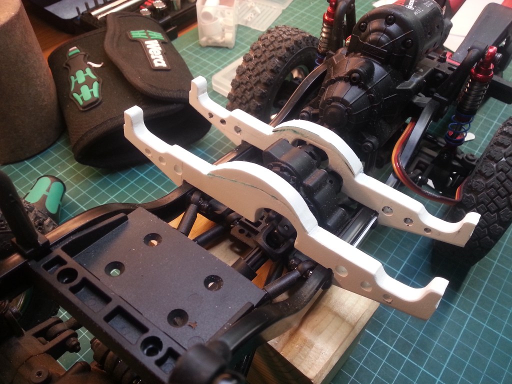
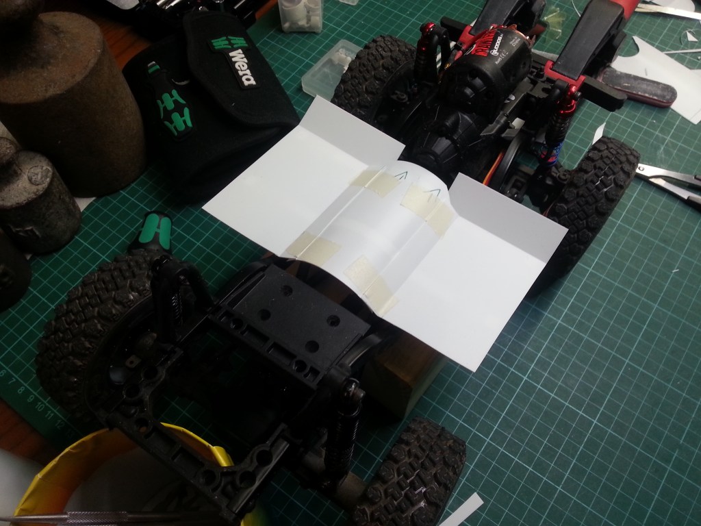
Hier an ihrer späteren Position, aufgesattelt auf den Rahmenprofilen. Man erkennt rechts am Rahmen einen der Kunststoffstreifen, die den Hilfsrahmen an den Befestigungsschrauben des Verteilergetriebes fixieren.
Seitlich des Kardantunnels werden die Bodenplatten aufgelegt. Vorne steigen sie schräg zur Feuerwand an, wie auch beim Original.
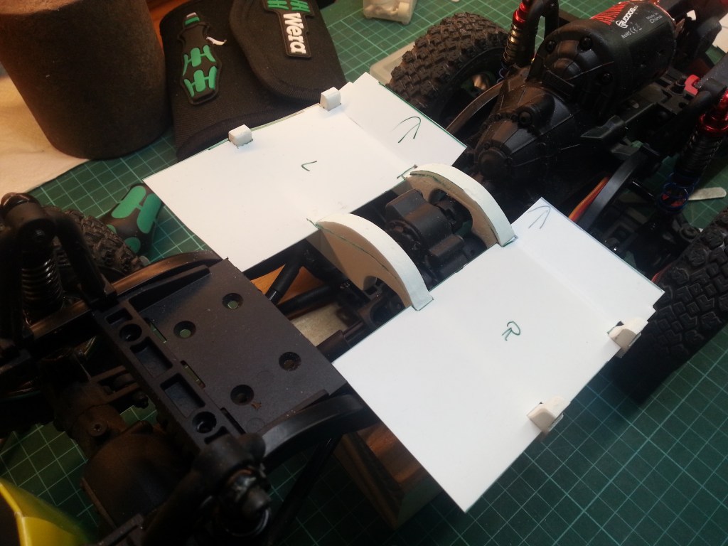
Die Feuerwand wurde auch schon grob an ihrem Platz unter der Frontscheibe eingepasst.

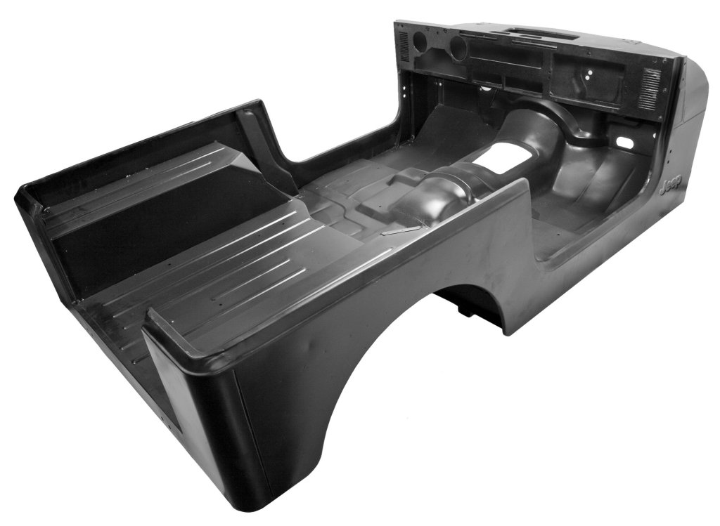
Eine wunderbare Vorlage des Ensembles, habe ich auch dazu im Internet gefunden. Da gibt es also noch einiges zu bauen. 😉
Wenn auch bei diesem Modell ohne Strukturierung des Bleches. Es wird später einen Teppichboden bekommen. Das Ziel für dieses Projekt, ein Schönling, mit viel Chromglanz und Bling-Bling. Einen Jeep Wrangler als Wettkampf-Crawler, mit viel nacktem und auf das nötigste reduzierte Blech, könnte ich mir aber in der Zukunft auch noch vorstellen…😏
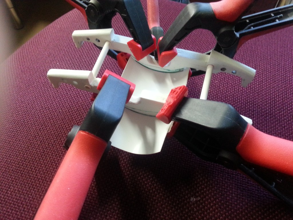
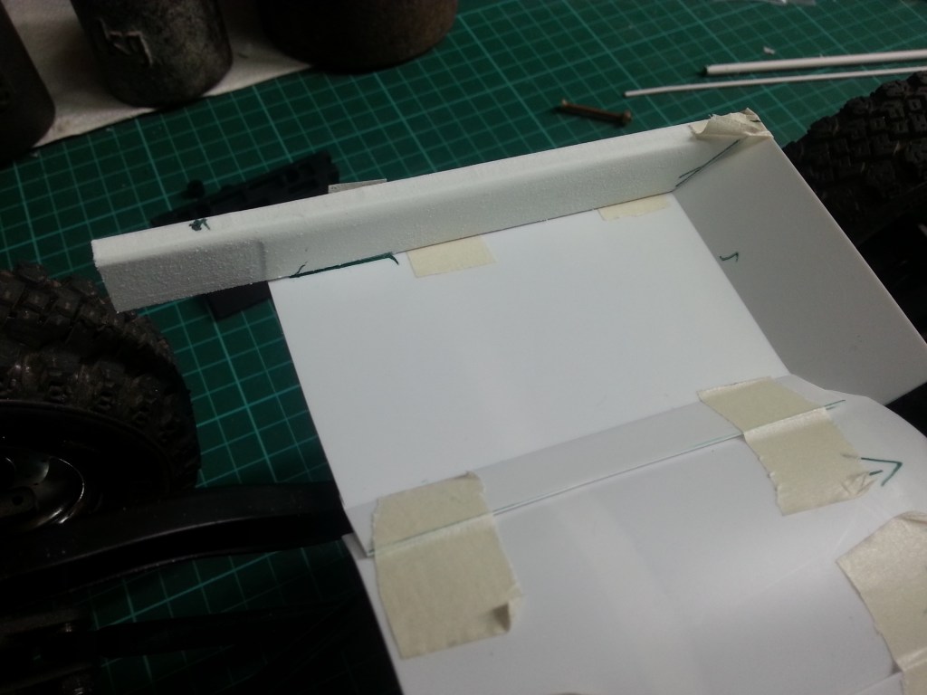
Die Verkleidung des Kardantunnels war der nächste Bauschritt. Auch 0,5 mm dünne PS-Platten haben eine Eigendynamik und mussten mit Spannern am Platz gehalten werden. Zwei 5 mm PS-Rohre habe ich vorher als Abstandshaltern in den Hilfsrahmen gesteckt, um die Konstruktion zu stabilisieren.
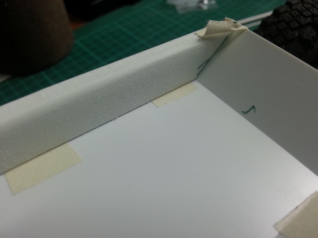
Nach der Fixierung wurde noch Änderungen am Hilfsrahmen und dem „Bodenblech“ vorgenommen. Das war zum einen optimaler herzustellen und letztlich auch weniger aufwändig. Sowohl das vorne aufsteigende Fußteil, als auch die seitliche Verbindung zum Kardantunnel wurden von unten angeritzt und abgeknickt. So entstanden schönere Übergänge. Später verklebt, auch optisch eine nahezu durchgehende Bodengruppe.
So dann die neue Innenansicht. Ich überlege bereits wie der nächste Bauschritt herzustellen ist. Der Fahrerfußraum muss nach vorne erweitert werden. Zudem soll auch der obere Abschluss des Kardantunnels verschlossen werden. Eine äußerst schwierige Angelegenheit. Dreidimensionaler Bau mit Anspruch.
Weiter müssen die Übergänge von der Bodengruppe zu den Türen hergestellt werden. Um dann eine Stufe zum Gepäckraum zu bauen. Die Radkästen sind eckig und reichen von der Hecktür bis fast zu den Sitzlehnen.

Die seitlichen Schweller, zur Verstärkung der Bodengruppe, war der nächsten Schritt. Aus einer 8 mm dicken Forex-Platte wurden sie gefräst. Mit einem 40° Winkel, als vorderem Abschluss zum Fußraum.
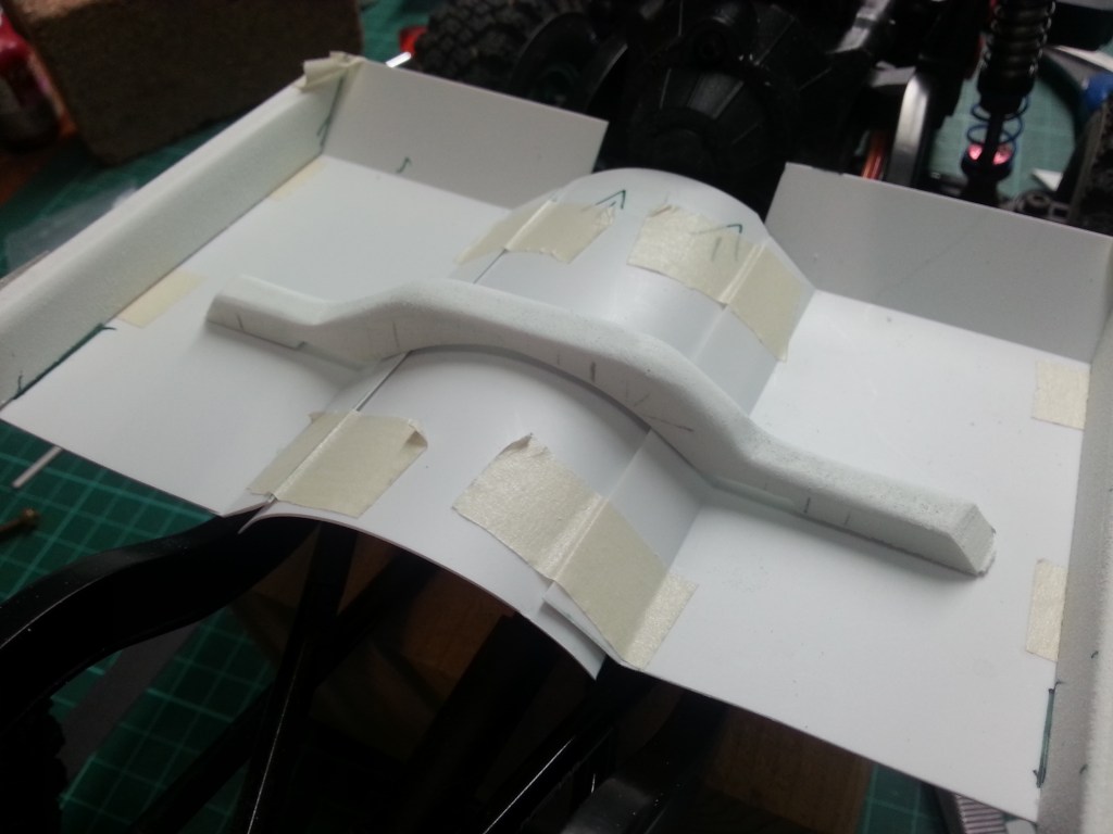
Dann habe ich ein kleines Bauteil begonnen. Einer Verstärkungsstrebe, die wohl das Getriebe im Kardantunnel trägt. Eigentlich für einen Wagen mit Teppichboden völlig überflüssig. Meine Leidenschaft beim Basteln kennt aber bisweilen keine Grenzen. Ich legte wie so oft los und das Ergebnis faszinierte mich.
Ein weiteres Bauteil kam dazu. Der hintere Abschluss des Tunnelprofils. Aus zwei 8 mm starken Forex-Platten verklebt…
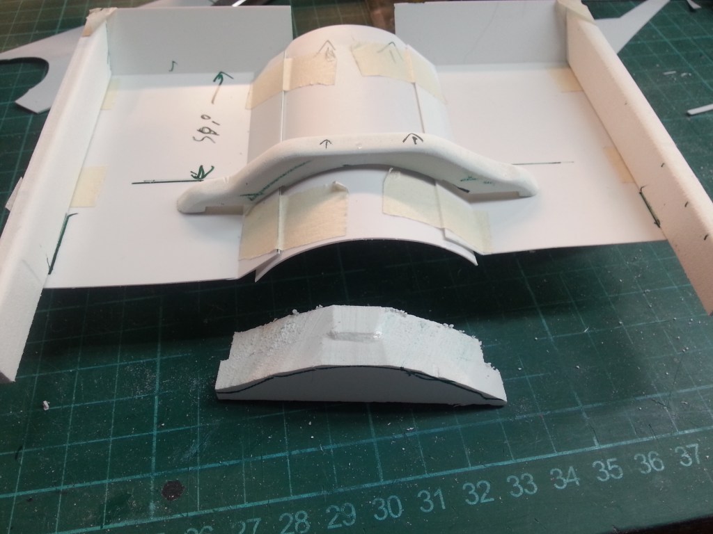
… innen und außen abgerundet. Sehr viel Schleifarbeit!

Schließlich noch ein weiteres Teil, nicht sonderlich aufwändig, aber dafür mit hohem Zeitaufwand.
Jetzt war mein Basteltrieb völlig entfacht. Meine ursprüngliche Idee einen Straßen-Crawler zu bauen, stand auf der Kippe. Das nachfolgende Zwischenergebnis, könnte der Weg zu einem sportlichen Jeep Wrangler werden, gänzlich ohne Inneneinrichtung. Das habe ich ja auch schon beim Comanche Truggy in Arbeit. Der Reiz etwas zu bauen, was es in der Form nicht oft gibt, brennt wieder in mir…

An diesem Punkt ist dann eine Entscheidung gefallen. Die bisherige Baustrategie scheint zu funktionieren. Forex-Platten in der benötigten Stärke und Größe zusammenkleben und dreidimensional bearbeiten. Daher wieder einmal lange gebaut und doch wieder verworfen. Aus vielen Einzelteilen und einer Woche Arbeit entstand schließlich ein neues Ergebnis. Eine Bodenplatte aus dem Vollen gefräst und geschliffen. Basis war eine 10 mm starke Forex-Platte. Ich war mit dem Bauen derart beschäftigt und angespannt, dass leider keine Detailbilder während des Bauens entstanden sind. Sie folgen aber dem Muster wie eingangs beschrieben und dokumentiert. Daher das vorläufige Ergebnis in Kurzform…🤷♂️
Als nächstes baue ich den hinteren Innenraum, der etwas erhöht hinter den Sitzen beginnt. Darunter, zwischen den Rahmenprofilen, habe ich die Verbindungsbrücke zwischen den Stoßdämpferdomen entfernt. Hier kann nur ein kompaktes Akku untergebracht werden. Ein Shorty Akkupack in 2s Ausführung, mehr ist platztechnisch ohne Verlust meines geliebten Innenraums, nicht unterzubringen.
Nach Fotos der Bodengruppe, habe ich versucht ein entsprechendes Bild der Oberseite zu fräsen. Kardantunnel, der Abschluss zum Motorraum und ein Blechprofil über der Kardanwelle, entstanden aus separat gebauten Teilen. Rechts also die Bodengruppe von unten und links meine daraus erstellt Gegenseite. Darüber der komplette Innenraum. Weitere Details in der Blechstruktur folgen noch.

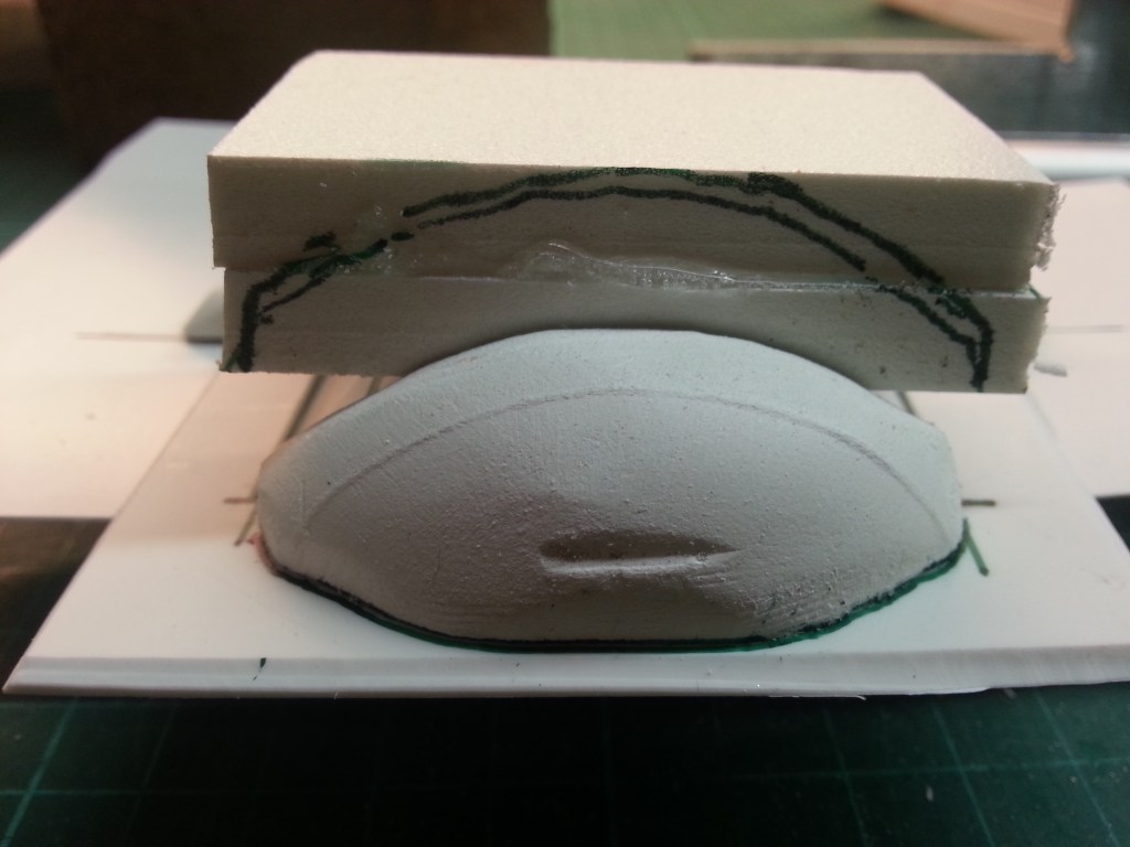
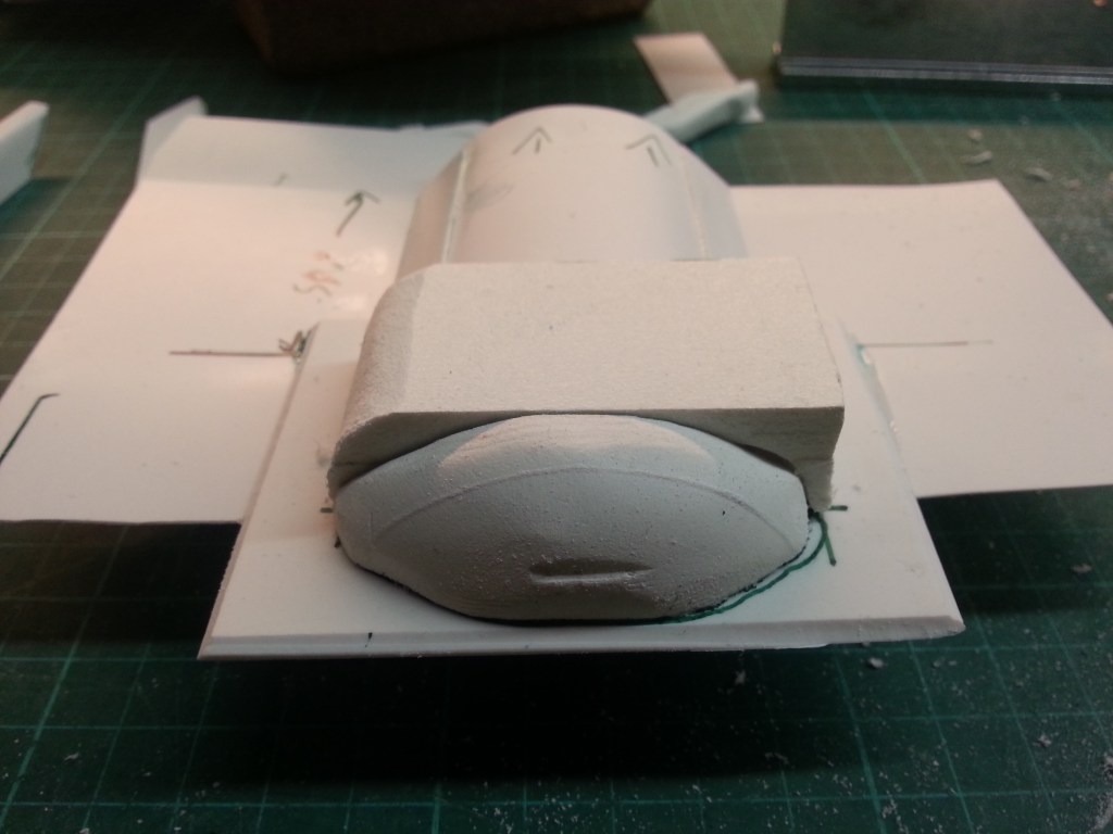
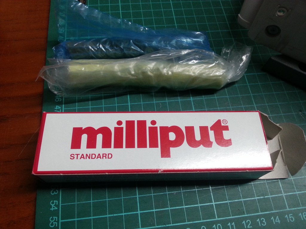
Ein sehr schieriges Bauteil stand noch im Raum. Der aufsteigende vordere Abschnitt des Kardantunnels, bis zur Feuerwand. Dazu wieder Forex-Platten in Stufen und lagenweise verklebt. Die Stützkonstruktion des vorderen Kardantunnels entstand aus kleinen, individuell angepassten Teilen. Sofern die Fußstützen und der Kardantunnel verklebt sind, werde ich hier noch einmal Struktur hineinbringen. Dazu werden einige Ecken wieder entfernt und die Kontur des oben bereits angedeuteten Kardantunnels nach unten fortgesetzt. Die jetzt noch sichtbaren Einblicke in den Innenraum werden mit Milliput verschlossen. Am oberen Rand des Kardantunnels habe ich damit bereits begonnen. Der dort verwendete 0,5 mm Kunststoff spart zwar Gewicht, ist aber nur bedingt schleifbar. Das abgebildete Bauteil wiegt derzeit 75 Gramm.
Nach dem ersten Einsatz von Milliput Spachtel ist das Ergebnis schon recht gut gelungen. Das 2-Komponentenmaterial wird mindestens 5 Minuten gründlich durchgeknetet und kleine Streifen in die Ecken gedrückt. Unter Wasser lässt sich alles glätten und final formen. Es ähnelt dann sehr der Tonverarbeitung. Gummihandschuhe sind dabei aber Pflicht!
Weitere weiche Ausformungen der Konturen folgen. Ziel ist es, die Optik fließend wie ein Pressteil aussehen zu lassen. Ich glaube das könnte so auch gelingen.
Der Innenraum nähert sich einer realen Optik. Dieses Mal nicht ganz exakt nach dem Original, nur vorbildähnlich. Die Umsetzung von einem eindimensionalen Bild auf dreidimensionale Optik, ist mit dem Koordinatentisch und meinem Fräsmotor nicht ohne. Einige Fehler beim Fräsen, wurden bereits mit neuen Frästeilen nachgebessert.
Im Innenraum dann dieses Bild, für heute sozusagen der Abschluss.


Wird schnellstmöglich fortgesetzt…
English Version
Interior fittings Jeep Wrangler YJ
Sources: RC-HP, Internet image search
There are a few construction sites in my workshop. How and when I build them is up to me. The reason for building the Jeep Wrangler again is quite banal. RC HP supplied the inserts adapted to the vehicle weight and tyre size. A service that is very rarely available today. In the first report on the driver test I still tried to drive with the original RC4WD inserts. The result; two tyres peeled off the rim. But I had also used a mounting aid, in the form of washing-up liquid. Now the re-mounting, but without any aids. A first dry run absolutely confirmed the effect of the new inserts. A tyre that deforms under load and yet sits absolutely stable on the rim.
The reason for the dry run is that I have opened another construction site in the meantime, the removal of the interior. The very small interior of the two-seater leaves hardly any options for accommodating the battery and electronics. At least not if things are to be done reasonably realistically. All the previously installed electronics had to be removed. When it comes to accommodating the battery, things will be very tight and I will have to supplement my battery pool with more compact models.
But let’s stay in order. Since I plan to be able to separate the body from the base plate, a stable support construction had to be built. Once not exactly according to the original, because then a stable but heavy base plate would be necessary to hold everything on the frame. To save weight, I only use 0.5 mm thick PS plates. Technically, however, it should look the part and so I built these two constructions. Later they sit on the frame, connected with two PS strips and these are each screwed to the side of the frame.
Here at their later position, mounted on the frame profiles. On the right side of the frame you can see one of the plastic strips that fix the subframe to the mounting bolts of the transfer case.
At the side of the cardan tunnel the floor plates are placed. At the front they rise diagonally to the firewall, like on the original.
The fire wall has already been roughly fitted in its place under the windscreen.
I also found a wonderful model of the ensemble on the internet. So there is still a lot to build 😉 .
Even though this model has no textured sheet metal. It will get a carpet later. The goal for this project, a beau, with lots of chrome shine and bling bling. But I could also imagine a Jeep Wrangler as a competition crawler in the future, with a lot of naked sheet metal reduced to the bare minimum…😏
The cladding of the gimbal tunnel was the next construction step. Even 0.5 mm thin PS sheets have a momentum of their own and had to be held in place with clamps. I put two 5 mm PS tubes into the subframe beforehand as spacers to stabilise the construction.
After fixing, changes were made to the subframe and the „bottom plate“. On the one hand, this was easier to make and, on the other hand, it was less complicated. Both the foot part rising at the front and the lateral connection to the cardan tunnel were scored and bent from below. This resulted in more beautiful transitions. Later glued, also optically an almost continuous floor assembly.
This is the new interior view. I am already thinking about how to build the next step. The driver’s footwell has to be extended to the front. In addition, the upper end of the gimbal tunnel has to be closed. An extremely difficult matter. Three-dimensional construction with ambition.
Furthermore, the transitions from the floor assembly to the doors have to be made. Then a step to the luggage compartment has to be built. The wheel housings are angular and extend from the rear door almost to the seat backs.
The side sills, to reinforce the floor assembly, was the next step. They were milled from an 8 mm thick forex plate. With a 40° angle, as a front end to the footwell.
Then I started a small component. A reinforcement strut, which probably carries the gearbox in the cardan tunnel. Actually for a car with carpeting completely superfluous. But my passion for tinkering knows no bounds. I started as I often do and the result fascinated me.
Another component was added. The rear end of the tunnel profile. Glued together from two 8 mm thick Forex panels…
… rounded on the inside and outside. A lot of sanding work!
Finally, another part, not very elaborate, but very time-consuming.
Now my tinkering instinct was completely ignited. My original idea of building a street crawler was on the back burner. The following interim result could be the way to a sporty Jeep Wrangler, without any interior at all. I already have that in the works with the Comanche Truggy. The attraction of building something that doesn’t often exist in this form is burning inside me again…
At this point a decision was made. The previous building strategy seems to work. Gluing together forex panels in the required thickness and size and working them three-dimensionally. So once again I built for a long time and then discarded it. Finally, a new result emerged from many individual parts and a week’s work. A base plate milled from the solid and sanded. The basis was a 10 mm thick forex plate. I was so busy and tense with the building that unfortunately no detailed pictures were taken during the construction. But they follow the pattern as described and documented at the beginning. Here is the preliminary result in short form…🤷♂️
Next I build the rear interior, which starts slightly raised behind the seats. Underneath, between the frame profiles, I have removed the connecting bridge between the shock absorber domes. Only a compact battery pack can be accommodated here. A Shorty battery pack in 2s version, more is not to be accommodated without losing my beloved interior space.
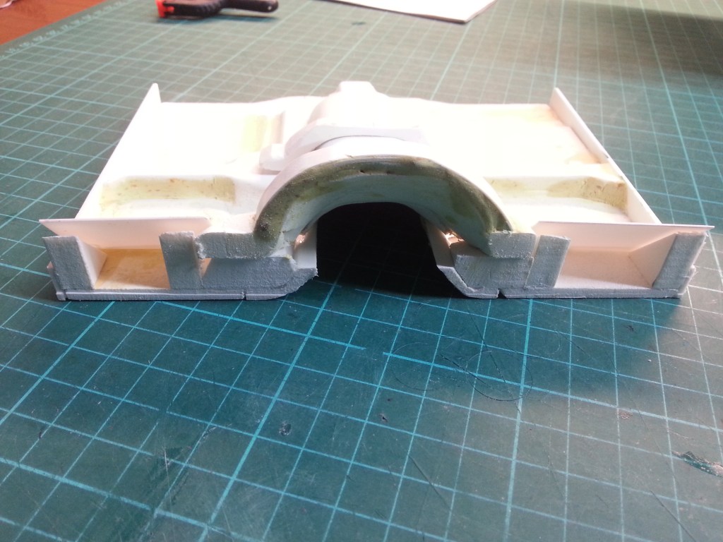
After taking photos of the floor assembly, I tried to mill a corresponding picture of the top. The gimbal tunnel, the end to the engine compartment and a sheet metal profile above the gimbal shaft were made from separately built parts. On the right the floor assembly from below and on the left the opposite side. Above the complete interior. Further details in the sheet metal structure will follow.
A very difficult part was still to be built. The ascending front section of the gimbal tunnel, up to the firewall. For this again forex plates in steps and glued in layers. The supporting construction of the front gimbal tunnel was made of small, individually adapted parts. As soon as the footrests and the cardan tunnel are glued, I will add some structure here. To do this, some corners will be removed again and the contour of the cardan tunnel already indicated above will be continued downwards. The glimpses into the interior that are still visible will be closed with Milliput. I have already started on the upper edge of the cardan tunnel. The 0.5 mm plastic used there saves weight, but can only be sanded to a limited extent. The component shown here currently weighs 75 grams.
After the first use of Milliput putty, the result is already quite good. The 2-component material is kneaded thoroughly for at least 5 minutes and small strips are pressed into the corners. Under water everything can be smoothed and finally shaped. It is then very similar to working with clay. But rubber gloves are a must!
Further soft shaping of the contours follows. The aim is to make the look flowing like a pressed part. I think this could be successful.
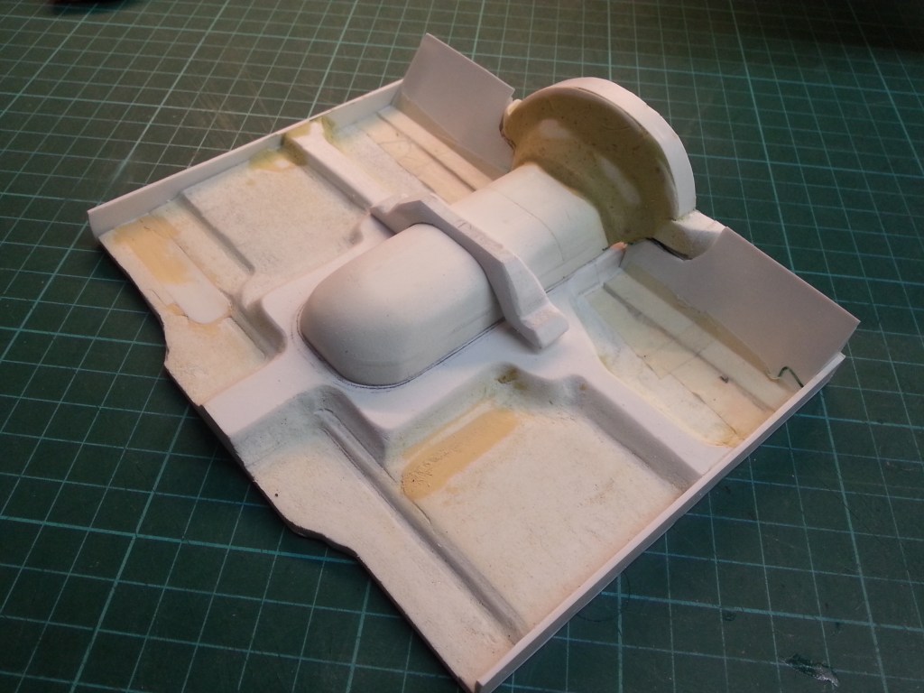
The interior is approaching a real look. This time not exactly according to the original, only similar to the model. The conversion from a one-dimensional picture to a three-dimensional look is not easy with the coordinate table and my milling motor. Some mistakes during the milling process have already been corrected with new milling parts.
This picture is the final one for today, so to speak.
Will be continued as soon as possible…
Translation, with the kind support of deepl.com
