Quellen:
English Version
Manches Mal träume ich so in den Tag. Ich genieße einen Kaffee und erfreue mich am Blau des Himmels, der Sonne die hinter dem Berg aufsteigt und langsam die Schatten in unserem Tal vertreibt. Ich grübele über bereits gebautes und auch zukünftiges. Gedanken nach dem wie und wann, der Verfügbarkeit von Material. Und so baute ich eines Morgens in Gedanken eine Kabeltrommel. Ein recht einfach aufgebautes Werkzeug und doch nicht ohne. So beschäftigte mich die Herstellung der vielen dazu benötigten Bauteile. Da es ja möglichst realistisch sein sollte auch die Details, alles irgendwie nur rund und doch zweifelte ich auch an der Machbarkeit. Aber die Sache war beschlossen, nur wie realisieren. Hatte ich doch schon das eine oder andere Mal, ein Bauprojekt nicht so ernst genommen und einfach nur losgelegt. Dabei war ich über das Ergebnis oft selbst überrascht, also doch einfach wieder loslegen.
Als Muster stand mir nur meine alte Blech-Kabeltrommel zur Verfügung. Sie hat ausgedient und wird derzeit nur als Spender für Geräte gebraucht, die ein neues Gummikabel benötigen. So wird das Kabel immer kürzer. Meine aktuelle Kabeltrommel versorgt gerade irgendwo auf einem Campingplatz, den Wohnwagen meines Sohnes mit Energie.
So begann der Bau mit einem Lochschneider. Für den Maßstab 1:10 wurden zwei 32 mm große Scheiben aus einer 1,5 mm PS-Platte gesägt. Bei denen eigentlich auf Holz ausgelegten Schneiden, war das Ergebnis verbesserungswürdig, aber auch geplant. Soll es doch letztlich im Durchmesser kleiner werden, als jetzt ausgesägt.
Ein weiteres Ringelement wurde mit einer Kreisschablone aussen aufgezeichnet und einem Schälbohrer innen ausgebohrt. Ich nehme es einmal vorweg. Hätte ich anstelle der 2 gleich 4 Scheiben ausgesägt, hätte ich mir die nachfolgenden Schritte teilweise sparen können. Mit dieser Erkenntnis bin ich bei der nächsten Kabeltrommel etwas schneller fertig…😃
Eine Lexanschere diente also dazu, den Kreis auszuschneiden. Das ging nicht so exakt, wie ich das gerne gehabt hätte. Im nachfolgenden Bild sieht man, dass ich das Ringelement schon auf die Scheibe aufgeklebt habe. Alles auf eine gekürzte Schraube, mit Teilgewinde, gespannt und meine Hand-Bohrmaschine als Drehbank missbraucht. Gefühlvoll mit Flachfeile und Schmirgelpapier wurde so daraus eine perfekt kreisrunde Scheibe, mit verstärktem Rand. In der Mitte habe ich ein PS-Rohr mit 14 mm Durchmesser eingeklebt, jeweils eine linke und rechte Seite. Ein 12 mm PS-Rohr dient als Verbindungstück und passt perfekt in die 14 mm Rohrstummel. Das sieht dann so aus. Auch zu sehen, die beiden Messingbuchsen, Lager aus früheren Tamiya-Modellen, die seinerzeit durch Kugellager ersetzt wurden.
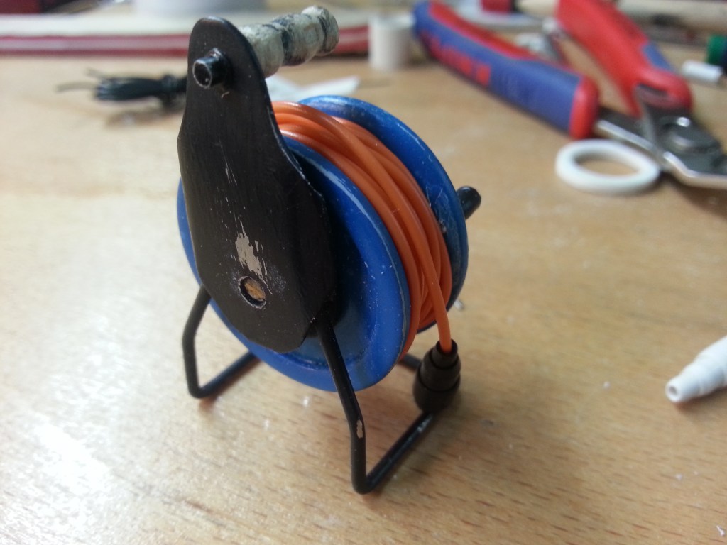
Montiert sieht das so aus. Hier ist das Innenrohr noch ungekürzt und diente nur zur Veranschaulichung.
Im Zentrum müssen nun drei Steckdosen untergebracht werden. In Deutschland und großen Teilen von Europa, gibt es den Schukostecker. Ausgeschrieben Schutzkontaktstecker. Darin gibt es zwei runde Kontaktstifte mit 4,8 mm Durchmesser, 19 mm Länge und 19 mm Achsenabstand für Außenleiter und Neutralleiter. Ein dritter Pol, der Schutzkontakt, soll Fehlerströme ableiten. Weiter will ich hier aber nicht auf die Technik eingehen.
Mein Problem, wie sollte ich das nachbauen? Die reale Schuko-Steckdose hat einen Innendurchmesser von ca. 48 mm und eine Tiefe von ca. 18 mm. Drei Stück sind auf einem Durchmesser von 12 mm unterzubringen, hier auf den ungefähren Maßstab heruntergerechnet. Es wird also sehr eng zugehen. Im Original steht etwas mehr Platz zur Verfügung, ich habe mich am Materialbestand orientiert, also kleiner als im Original. Den Vollkreis von 360° in drei Segmente von je 120° aufteilen. Auf meinem Zeichenbrett konstruierte ich daher eine ca. 14 mm kleine Papierschablone. Ja, manches Mal kommen mir auch Zweifel… 😯
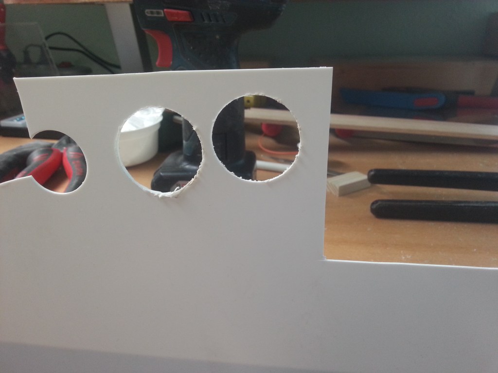
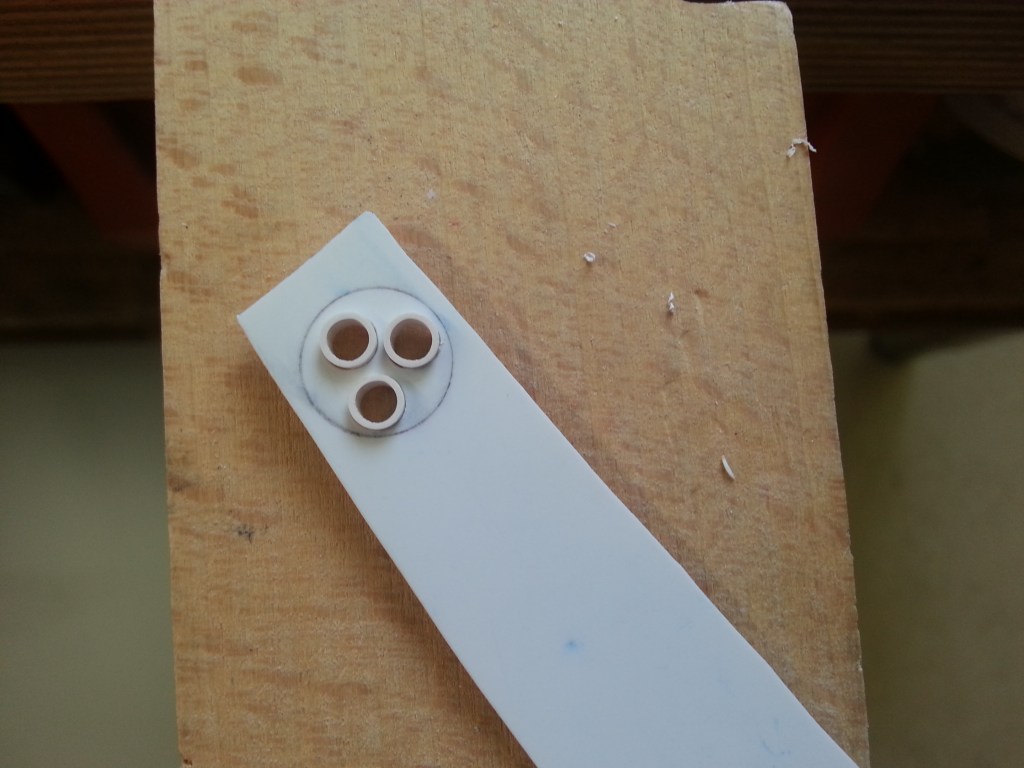
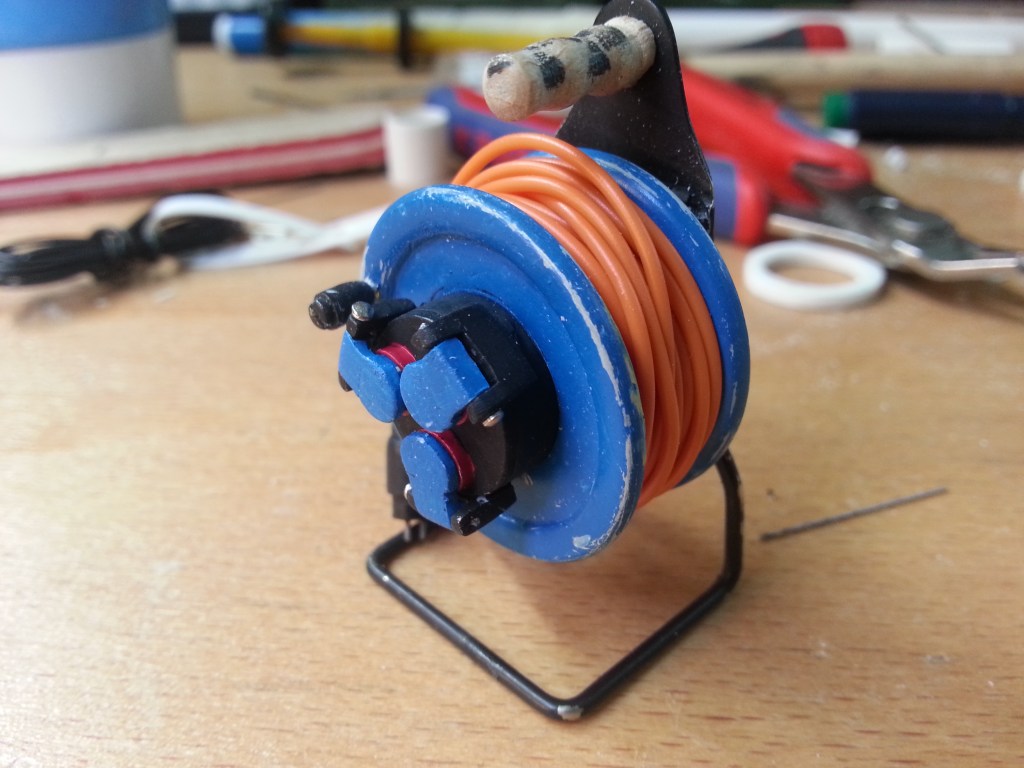
Ein Problem war, die Scheibe kreisrund zu bekommen und trotzdem die 3 Bohrung perfekt auszurichten. Mit nur einer zentrierten Bohrung könnte ich wieder meinen Kniff mit der Bohrmaschine verwenden, aber so eben nicht. Die Lösung, ein 12 mm Locheisen. Eine kreisrunde Klinge, die mit dem Hammer geschlagen, ein entsprechendes Loch ausstanzt. Das Teil wird später farblich abgesetzt, so dass jede Ungenauigkeit sofort sichtbar würde. Hier aber zunächst der Versuch das einmal mit der konventionellen Methode zu versuchen, mit minimaler Unschärfe beim Übertragen der Bohrungsmittelpunkte. Ja nach Perspektive sollte das aber später nicht mehr auffallen. Die eingeklebten Röhrchen haben einen Außendurchmesser von jeweils 5 mm.
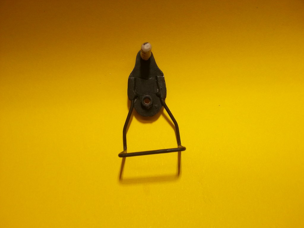
In der Trocknungszeit des Klebers habe ich mit dem Gestell begonnen. Gebogen aus 1,5 mm Silberdraht. Bei der Formgestaltung habe ich etwas Kreativität walten lassen. Das Rohrgestell wurde mit einem Stück Zinkblech verlötet. Das hatte ich passend ausgeschnitten, gefeilt und geschliffen. Eine Messingmutter M3, als Trommellager, wurde in der Bohrmaschine rund geschliffen und auch aufgelötet.
Mit einer Schraube M3 wird die Trommel später unsichtbar, hinter den Steckdosen befestigt. Die zentrale Rohrhülse und die beiden seitlichen Trommelscheiben werden nur gesteckt und nicht verklebt. In der Hülse stecken die zwei Messingbuchsen und in diesen ein 5 und ein 4 mm Kunststoffröhrchen. Darin die Schraube M3, die Trommel und Gestell miteinander verbindet.
Jetzt kam noch die Feinarbeit am Gestell und zum Schluss der Farbauftrag.
Für den Handgriff hatte ich mir etwas ausgefallendes überlegt, Holz. Lange schmale Reste der Stielproduktion waren ausreichend vorhanden. Ein solches in die Bohrmaschine eingespannt und langsam mit der Feile gerundet. Das ist zu Beginn wegen der Ecken etwas holprig, verändert sich aber in wenigen Sekunden zu einem gleichmäßigen Rundlauf. So habe ich übrigens auch die Messingmuttern „abgedreht“.
Ein weiteres Bauteil beschäftigte mich schon einige Tage zuvor. Wohl in einem Maß, dass sich meine Frau so ihre Gedanken machte. Ich schweifte ständig in Gedanken um die Machbarkeit des winzigen Teils, den Stecker am Ende der Kabeltrommel. Schließlich ging es dann an die Realisierung. Ganz so, wie ich es zu schaffen hoffte. Einen Satz Locheisen hatte ich schon bestellt, der war aber noch nicht eingetroffen und zu gerne hätte ich das Ergebnis meiner Überlegungen in die Tat umgesetzt. Ich bin das Risiko dann in Handarbeit angegangen. Das Steckergehäuse entstand aus einem 4- und 5mm Röhrchen.
Das innere Röhrchen lange genug, um es in das Bohrfutter einzuspannen. Wo es mit Schlüsselfeile und Schmirgelpapier seine Kontur erhielt. Im Bild der spätere Kabelausgang.
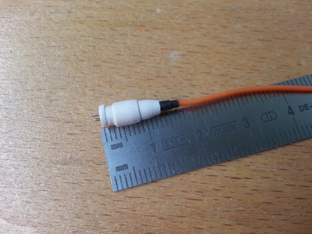
Der verdickte Handgriff wurde aufgeschoben, verklebt und ebenfalls geschliffen, um die gewünschte Steckerform zu bekommen. Das hatte also bisher wie geplant funktioniert, aber da war ja noch das Ende mit den beiden Steckkontakten. In meinem Schraubenfundus gibt es Microschrauben M 0,6 mit Vierkantkopf, die sollten dafür Verwendung finden. Die Scheibe des Steckerkopfes habe ich mit einer 5 mm Kreisschablone auf PS-Reste gezeichnet, die Löcher gebohrt und schließlich mit der Lexanschere ausgeschnitten. Nach einer guten halben Stunde mit einer Pinzette das Teil halten und der Schlüsselfeile auf ca. 4 mm herunterschleifen, sah das Ergebnis doch besser aus, als ich es mir je erträumt hätte. Schrumpfschlauch schaffte den Übergang zum Kabel.
Er sieht jetzt auch niedlich aus, aber gefällt mir so noch nicht. Ich musste also ein weiteres Modell bauen! Die erste Steckerausführung kommt in die Werkzeugkiste auf der Ladefläche, bearbeitet und lackiert natürlich. 🤷♂️
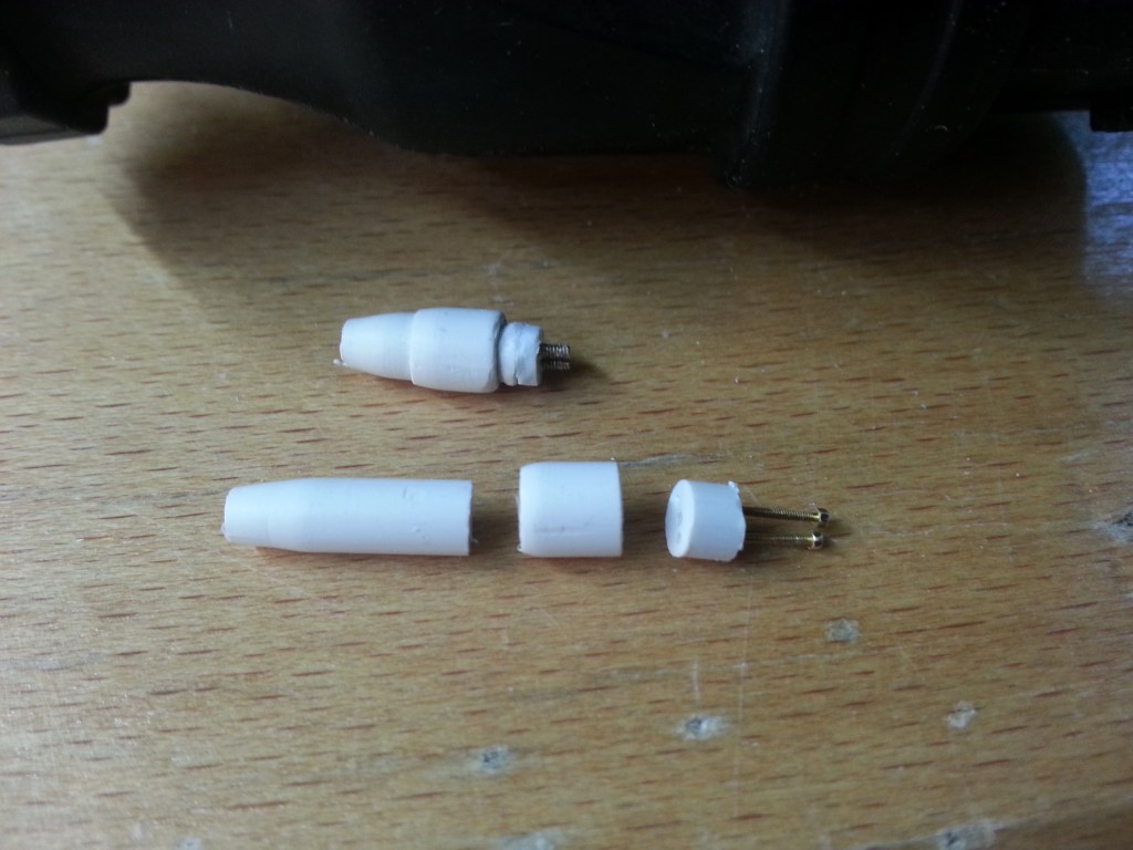
Der neue Stecker besteht nur noch aus Röhrchen und Stäben. Das ersparte mir viel Schleifarbeit und die Optik war so wie gewünscht harmonisch, fließend, wie aus einem Guss. Darüber das erste Modell
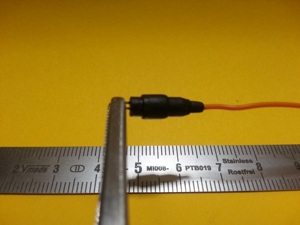
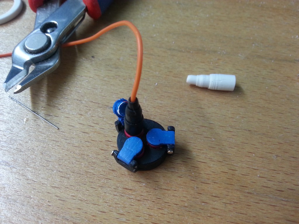
Nachfolgend der Stecker-Neubau, final beigeschliffen und lackiert. Im Stecker bereits das spätere Anschlusskabel! 🍾🥂

Für die letzten noch fehlenden Teile kam endlich die ersehnte Unterstützung, in Form von neuem Werkzeug. Einem Satz Locheisen. Die brauchte ich für die Klappdeckel der Steckdosen. Immerhin sollte der Spritzwasserschutz schon gewährleistet sein. Die Anspannung erreichte nunmehr einen neuen Höchstwert.
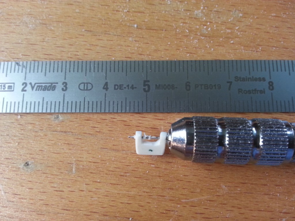
Ein ca. 4 mm kurzer Knauf, um die Trommel aufzuspulen, war der erste Schritt. Ein 4 mm Kunststoffstab, auch wieder ins Bohrfutter eingespannt, konisch angeschliffen, abgesägt und schließlich mit dem Mini-Handbohrer durchbohrt. Irgendwo in meiner Werkstatt liegen noch 4 solcher Teile. Wenn ich sie jemals wiederfinde, habe ich genug Vorrat für die nächsten Kabeltrommeln. 😂
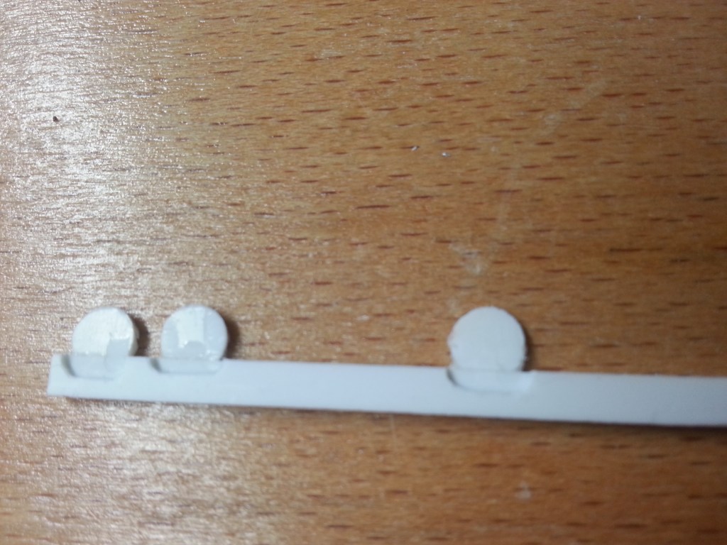
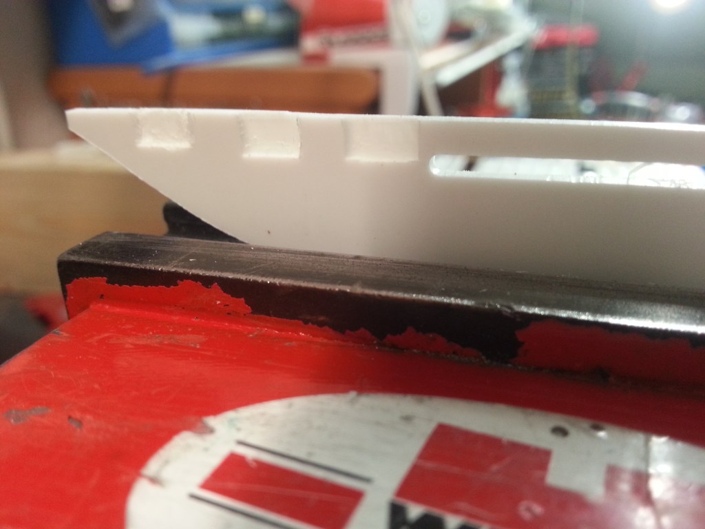
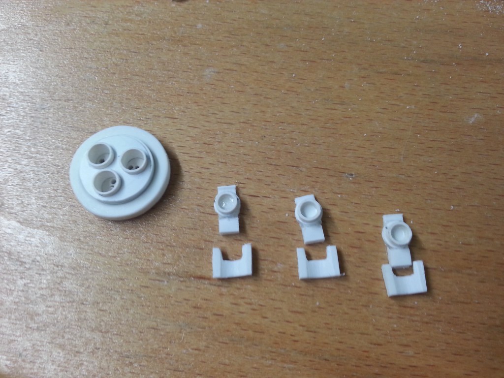
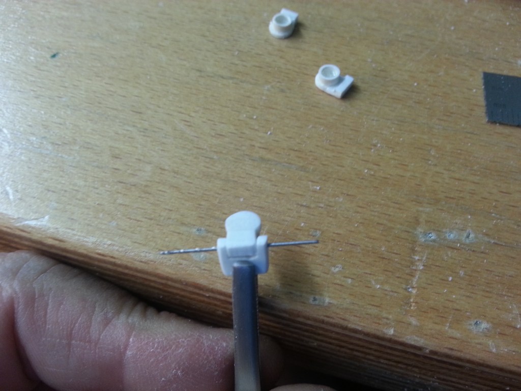
Die 5 mm im Durchesser und 1mm starken Klappdeckel wurden zuerst ausgestanzt. Nachdem ein Segment abgetrennt wurde, die Schnittkante mit einem 2 mm PS-Streifen verklebt. Daran habe ich wiederum eine Aussparung gefräst. Auf dem Foto die noch unfertige Version. Vermutlich muss für eine wirkliche Klappfunktion noch eine zweite dünne PS-Lage aufgeklebt werden. Die Klebefläche ist schon sehr klein.
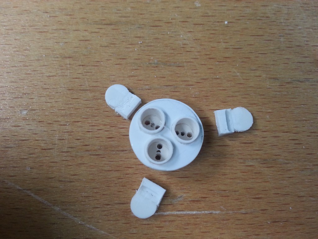
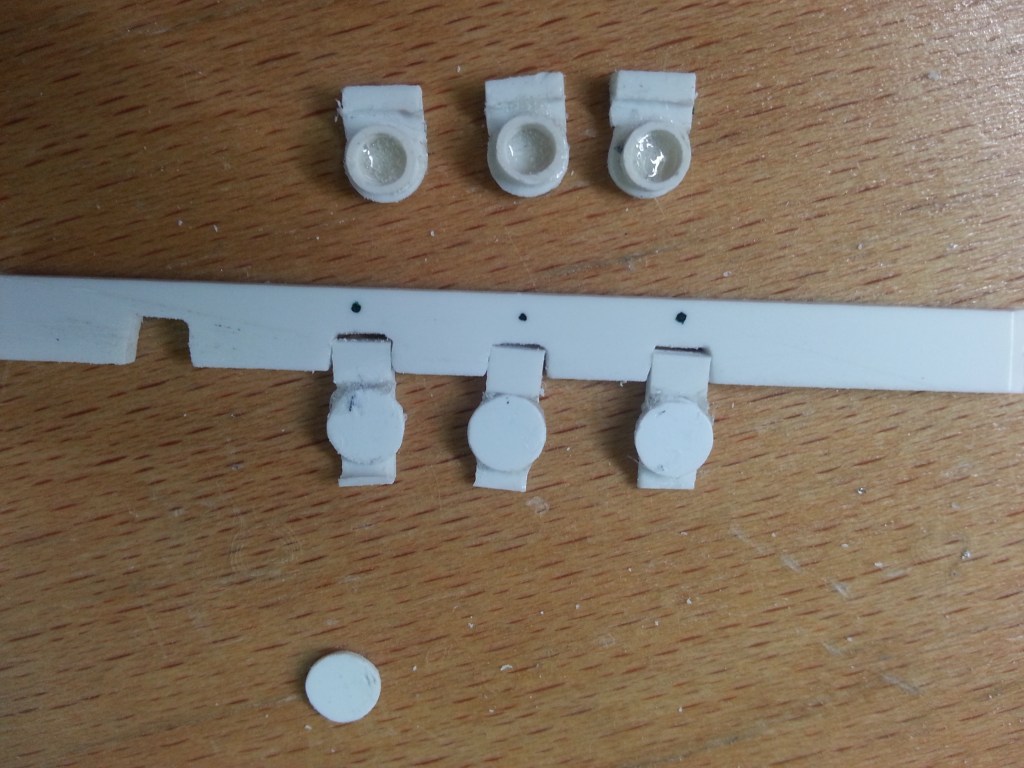
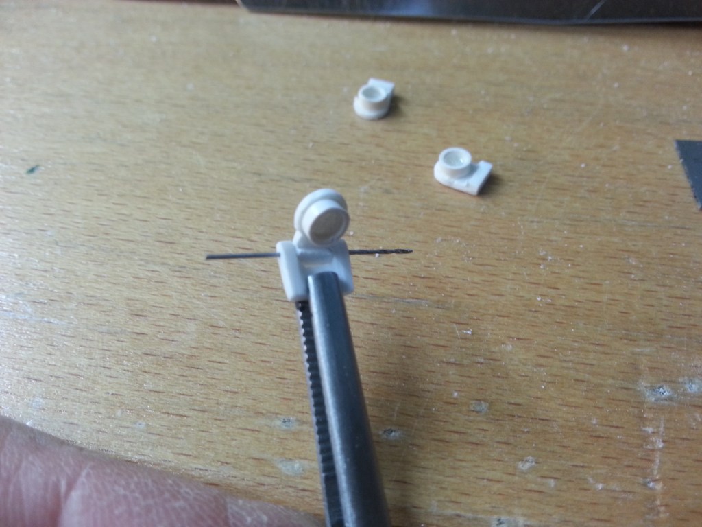
Die Leiste weiter in drei Abschnitte aufgetrennt.
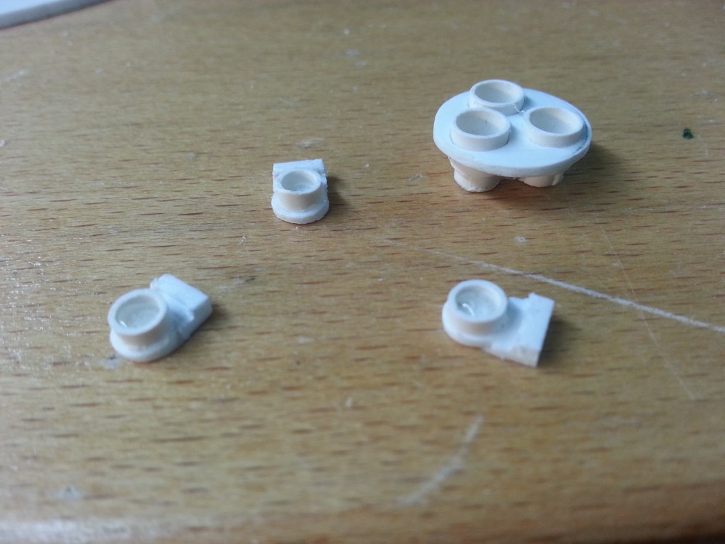
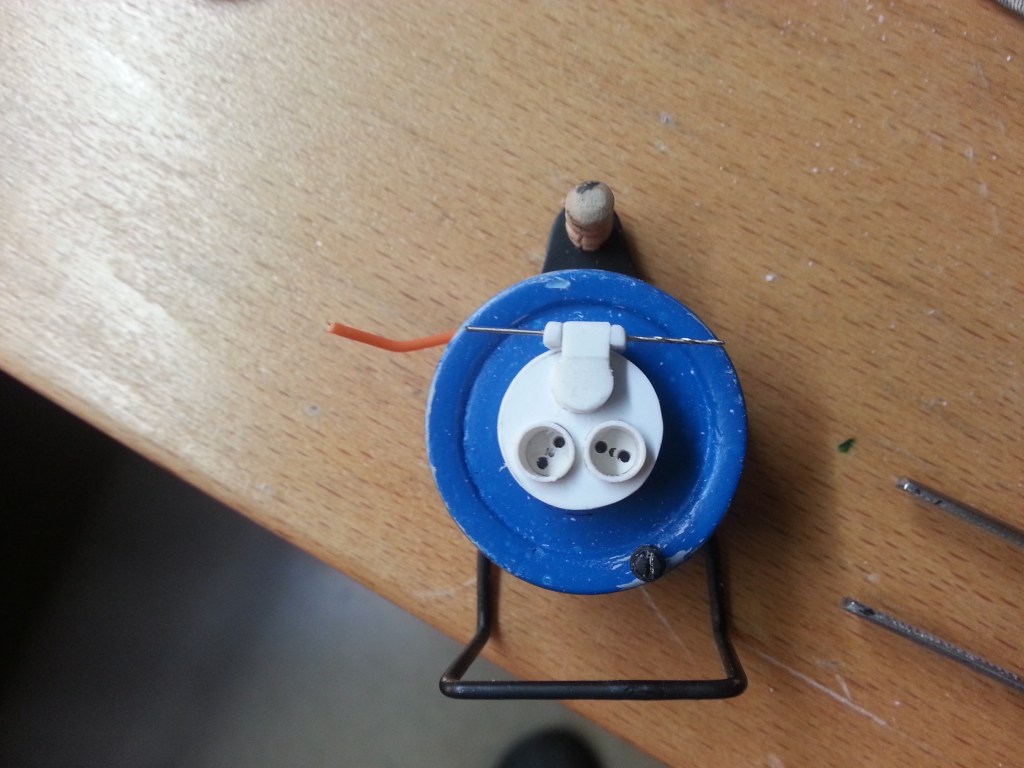
Ein aufgeklebter Rohrabschnitt dient zur Fixierung in der Steckdose. Wenn der Wunsch alles beweglich zu machen misslingt, bleibt mir so wenigstens die schöne Optik.
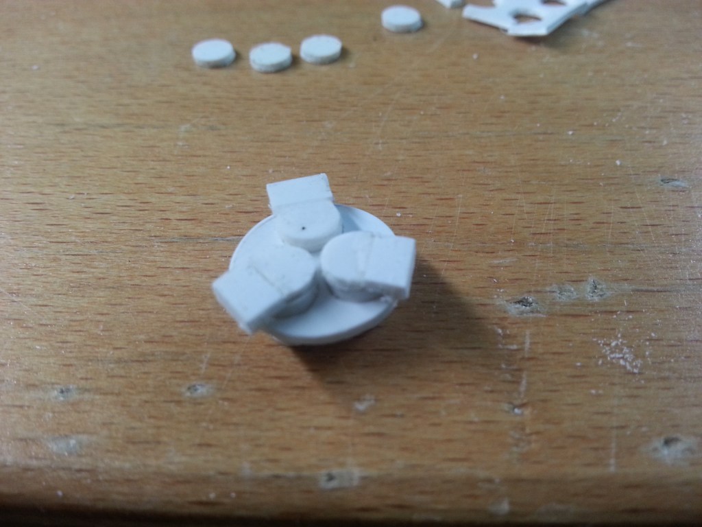
So sollte es dann zumindest geschlossen aussehen. Da liegt noch einiges vor mir, vor allen Dingen sehr viel Schleifarbeit…
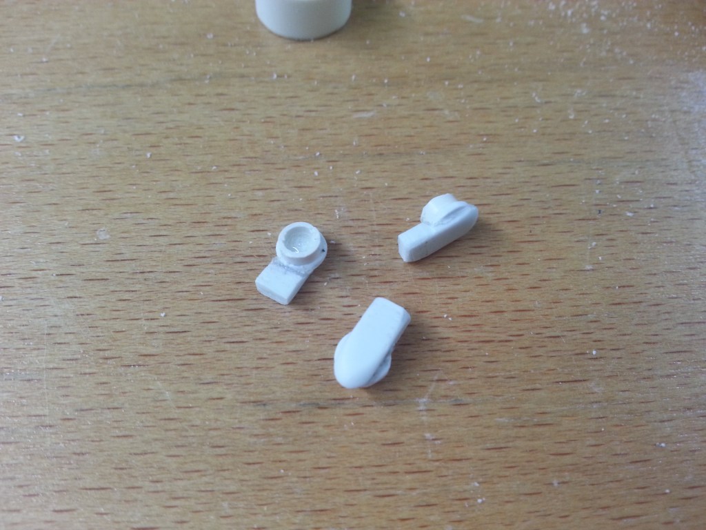
Für eine noch stabilere Version der Klappdeckel habe ich Taschen in einen 2 mm Streifen gefräst. Darin werden neue, runde Deckel aufgeklebt. Im nachfolgenden Foto zu sehen.
Doch der wichtigste Schritt, oder besser Versuch kam erst jetzt. In einem 2 mm PS-Streifen wurden Aussparungen herausgearbeitet, in denen später die Drehpunkte der Spritzwasserdeckel sitzen sollen. Alle Teile hier, sind noch nicht final bearbeitet.
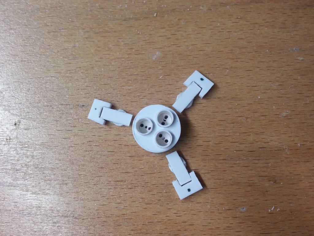
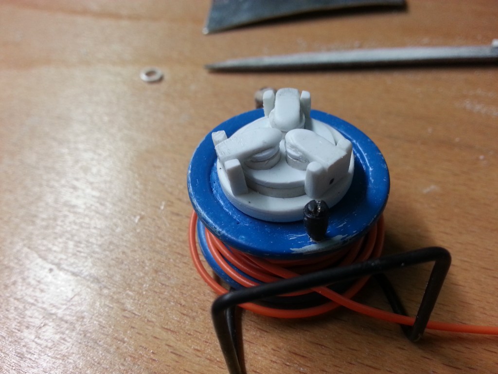
In die späteren Segmente aufgeteilt und probeweise angeordnet.
Um die Befestigungspunkte der Klappdeckel zu montieren, war noch ein weiteres Bauteil nötig. Der Rand um die Streckdosen wurde dafür weiter vergrößert. Alles nach bewährter Vorgehensweise.
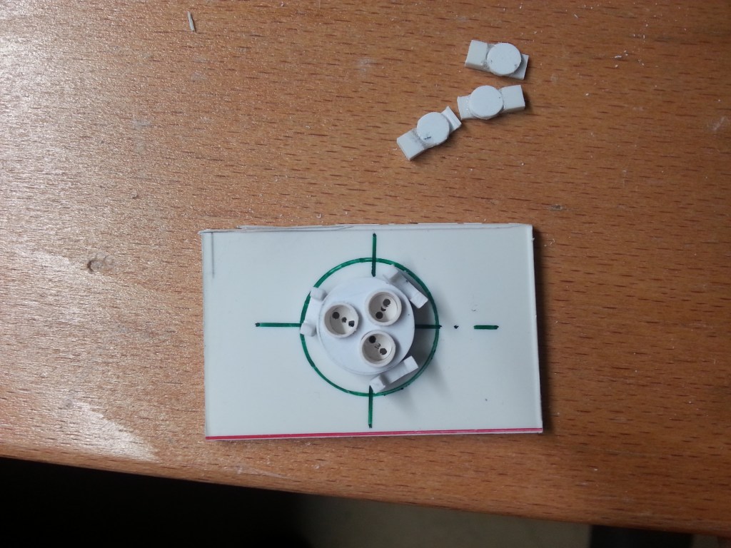
Wie schon bei der ersten Version, habe ich auch beim endgültigen Modell wieder Zentrierringe auf die Deckel geklebt. Da keine Sicherungen gegen unbeabsichtigtes Öffnen der Deckel vorgesehen sind, verspreche ich mir davon genau diesen Effekt. Im Bild auch der zusätzliche Ring für die Befestigung der Klappscharniere.
Nach langem und filigranem Schleifen, vorwiegend mit Schleifvlies, dass Ergebnis vor dem Bohren der 0,5 mm Achsen. Ich habe viele Bilder während des Bauens gemacht. Mit jedem Schneiden, schnitzen oder schleifen geht auch der Moment des Scheiterns einher. Die Abdeckkappen sind nur jeweils 8 x 4 mm groß.
An diesem Punkt befand ich mich plötzlich in einem Wechselbad der Gefühle. Der letzte Schritt, dass Bohren der Achsen ist greifbar nahe und wahrscheinlich auch machbar. Nach der ersten Euphorie kommt aber die Ernüchterung. Der zuletzt hergestellte Ring für die Klappenhalterung ist zu dick und groß, für die ansonsten so filigranen Bauteile der Kabeltrommel, wie auch die so aufwändig gefertigten Deckel. Jetzt brauchte ich einen Neustart.
🤓 Meine zuerst angefertigten Deckel kamen dadurch wieder ins Spiel. Dafür habe ich in die Halter 0,5 mm Löcher gebohrt.
Gleiches auch in den Klappen und das Ergebnis wie folgt. Mangels 0,5 mm Draht noch mit 0,5 mm Bohrern fixiert.
Der Anblick der Kabeltrommel entspricht nun so ganz meinen Vorstellungen. Der letzte Angstmoment ist nach einer Stunden Bohren und Schwitzen beendet.
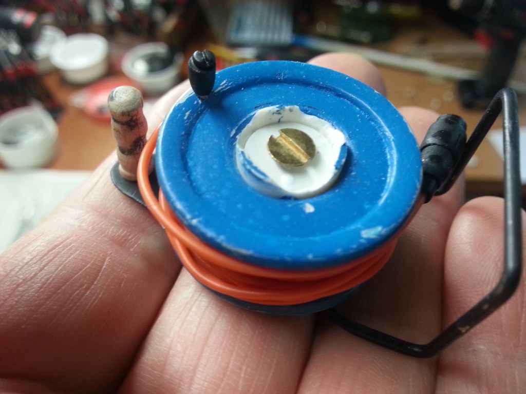
Final geschliffen und lackiert, die Galerie der kleinen Mikro-Kabeltrommel, ganze 19 Gramm leicht. Die Deckelachsen bestehen bis auf weiteres aus Stecknadeln.


Wird schnellstmöglich fortgesetzt…
English Version
Manufacture of loads and tools, Part 8-cable reel
Sources:
Sometimes I dream like this into the day. I enjoy a cup of coffee and take pleasure in the blue sky, the sun rising from behind the mountain and slowly dispersing the shadows in our valley. I think about what has already been built and what is to come. Thoughts about how and when, the availability of material. And so one morning I built a cable drum in my mind. A rather simple tool, but not without its own problems. So I was preoccupied with the production of the many components needed for it. Since it should be as realistic as possible, also the details, everything somehow only round and yet I also doubted the feasibility. But the matter was decided, only how to realise it. I had already taken one or two building projects less seriously and just got on with it. I was often surprised by the result myself, so I just started again.
The only sample I had available was my old tin cable drum. It has had its day and is currently only used as a dispenser for devices that need a new rubber cable. So the cable is getting shorter and shorter. My current cable drum is currently supplying power to my son’s caravan at a campsite somewhere.
So the construction started with a hole cutter. For the 1:10 scale, two 32 mm discs were sawn out of a 1.5 mm PS plate. With the cutters actually designed for wood, the result could be improved, but it was also planned. In the end it should be smaller in diameter than it is now.
Another ring element was drawn on the outside with a circular template and drilled out on the inside with a peeling drill. I’ll take it once in advance. If I had sawn out 4 discs instead of 2, I could have saved myself some of the following steps. With this knowledge, I’ll be finished a little faster with the next cable drum…😃
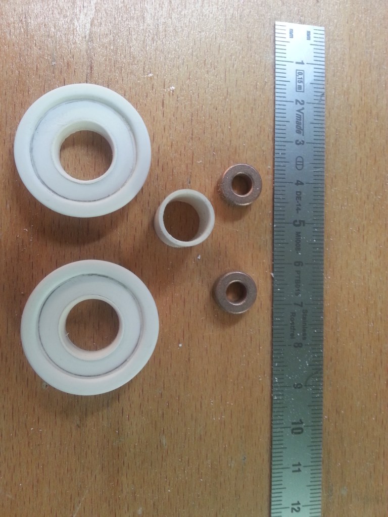
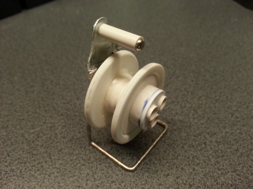
So a pair of lexan scissors was used to cut out the circle. This didn’t go as accurately as I would have liked. In the following picture you can see that I have already glued the ring element onto the disc. I clamped everything onto a shortened screw with a partial thread and used my hand drill as a lathe. I used a flat file and sandpaper to create a perfectly circular disc with a reinforced edge. I glued a 14 mm PS tube in the middle, one on the left and one on the right. A 12 mm PS tube serves as a connecting piece and fits perfectly into the 14 mm tube stubs. It looks like this. Also visible are the two brass bushings, bearings from earlier Tamiya models, which were replaced by ball bearings at the time.
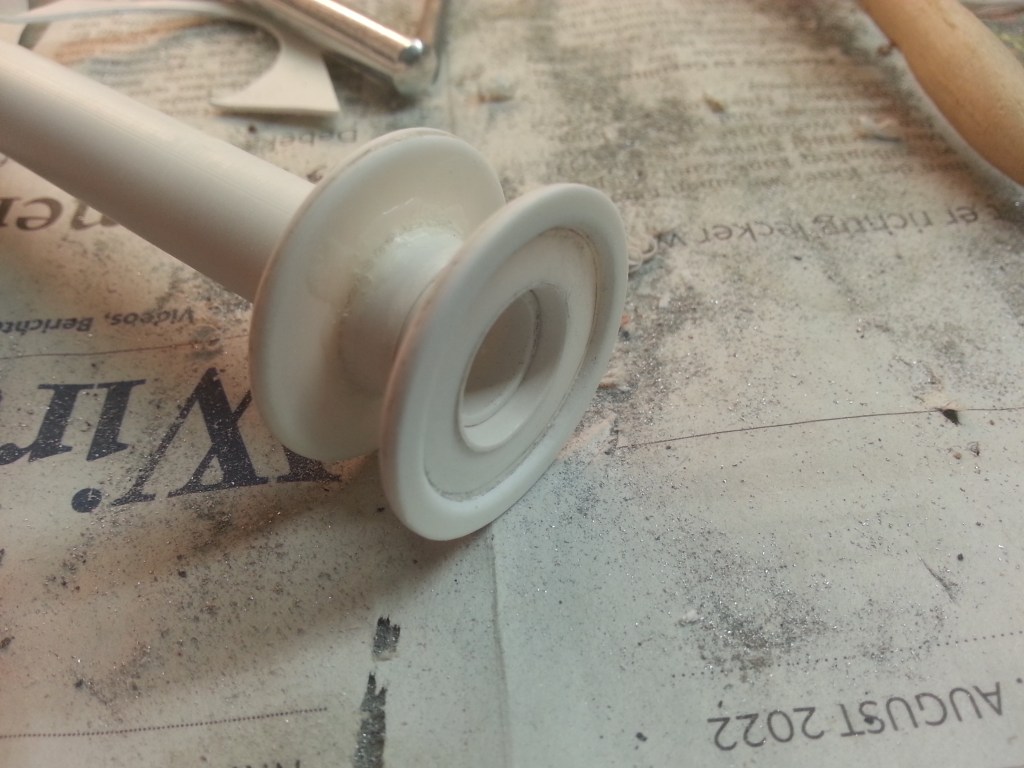
Mounted it looks like this. Here the inner tube is still untrimmed and was only used for illustration.
Now three sockets have to be placed in the centre. In Germany and large parts of Europe, there is the Schuko plug. It is called a safety plug. There are two round contact pins with a diameter of 4.8 mm, 19 mm length and 19 mm centre distance for the outer conductor and neutral conductor. A third pole, the earth contact, is intended to dissipate fault currents. But I don’t want to go into further detail about the technology here.
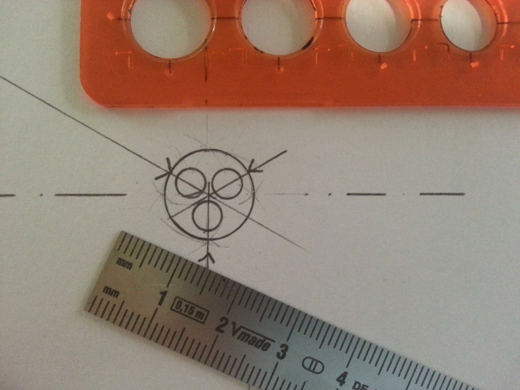
My problem, how should I reconstruct this? The real Schuko socket has an inner diameter of approx. 48 mm and a depth of approx. 18 mm. Three can be accommodated on a diameter of 12 mm, here calculated down to the approximate scale. So it will be very tight. In the original there is a little more space available, I orientated myself on the material stock, so smaller than in the original. Divide the full circle of 360° into three segments of 120° each. So on my drawing board I constructed a paper template about 14 mm small. Yes, sometimes I also have doubts… 😯
One problem was to get the disc circular and still align the 3 hole perfectly. With only one centred hole I could use my trick with the drill press again, but not like this. The solution, a 12 mm punch. A circular blade which, when struck with a hammer, punches out a corresponding hole. The part will be coloured later, so that any inaccuracy would be immediately visible. Here, however, is an attempt to try the conventional method, with minimal blurring when transferring the centre points of the holes. Depending on the perspective, this should not be noticeable later. The glued-in tubes have an outer diameter of 5 mm each.
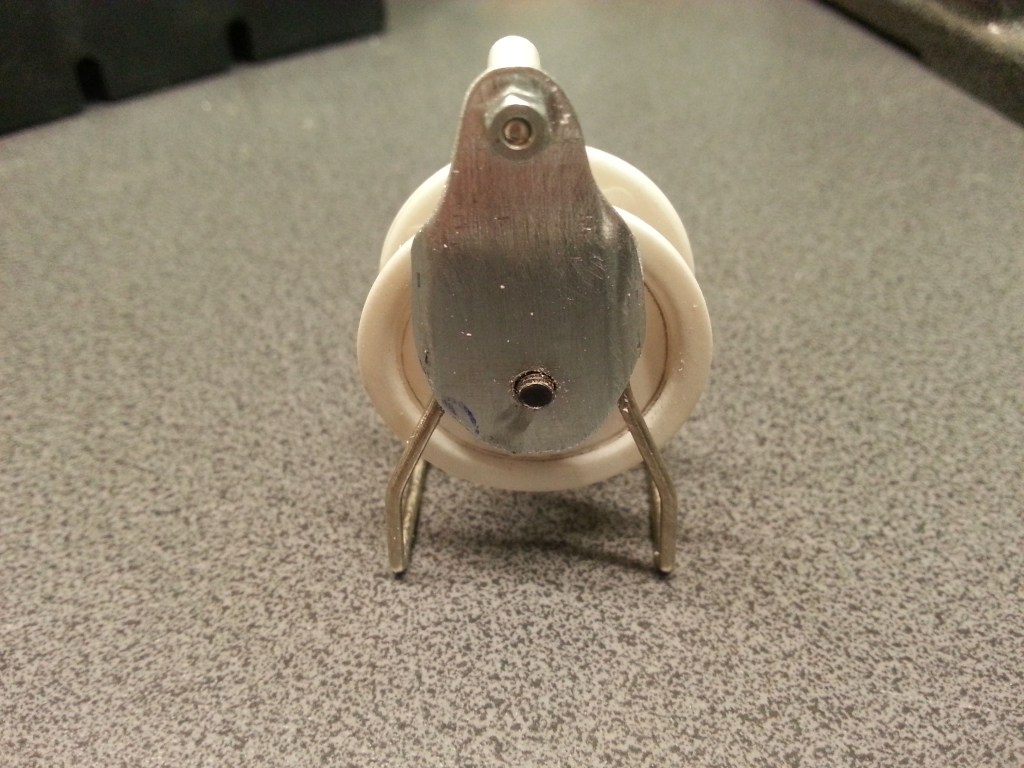
While the glue was drying I started with the frame. Bent out of 1.5 mm silver wire. I was a bit creative with the shape. The tubular frame was soldered to a piece of zinc sheet. I had cut it out, filed and polished it to fit. A brass nut M3, as a drum bearing, was ground round in the drill and also soldered on.
The drum is later fixed invisibly behind the sockets with an M3 screw. The central tube sleeve and the two lateral drum discs are only plugged in and not glued. The two brass bushes are in the sleeve and a 5 and a 4 mm plastic tube are in them. Inside are the M3 screws that connect the drum and the frame.
Now came the finishing work on the frame and finally the application of the paint.
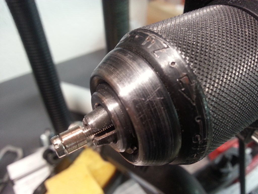
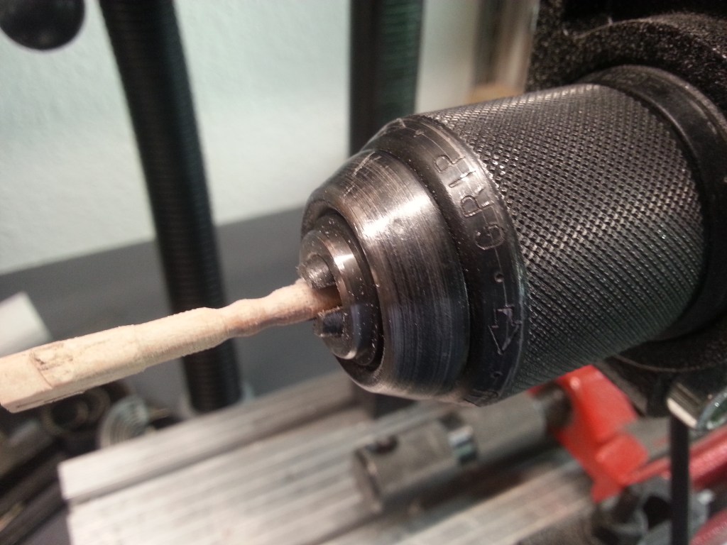
For the handle I had thought of something unusual, wood. Long narrow remnants of the handle were sufficiently available. I clamped one in the drill and slowly rounded it with the file. At the beginning it is a bit bumpy because of the corners, but in a few seconds it changes to a smooth roundness. By the way, this is also how I „turned“ the brass nuts.
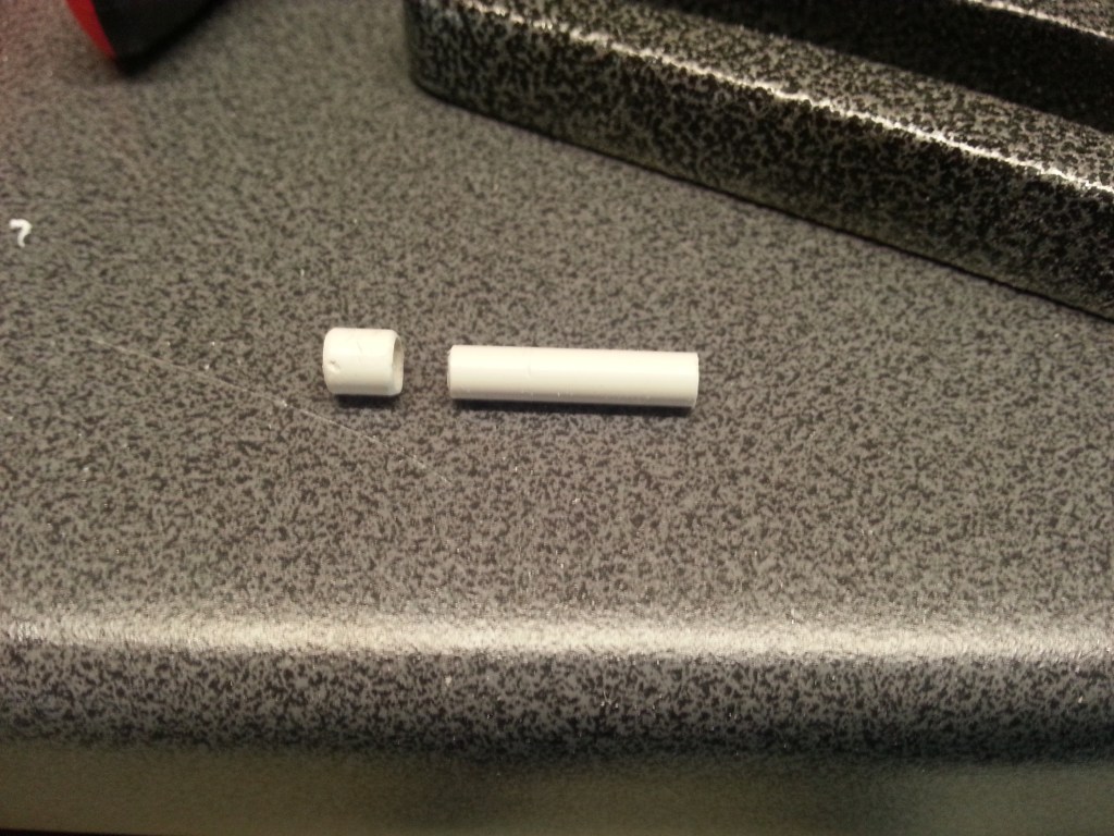
Another component kept me busy a few days before. Probably to such an extent that my wife was worried about it. I was constantly thinking about the feasibility of the tiny part, the plug at the end of the cable drum. Finally, it was time for the realisation. Just as I hoped to make it. I had already ordered a set of punching irons, but they hadn’t arrived yet and I would have loved to put the result of my thoughts into practice. I then took the risk by hand. The connector housing was made from a 4 and 5 mm tube.
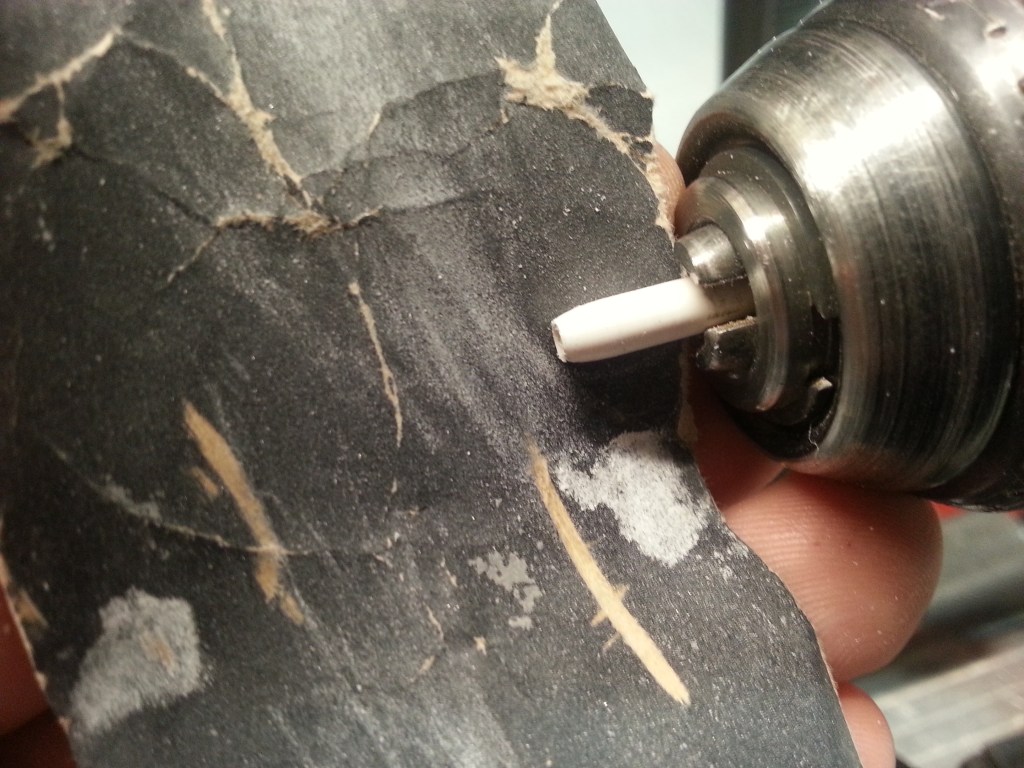
The inner tube long enough to clamp it into the drill chuck. Where it got its contour with a key file and sandpaper. The picture shows the later cable exit.
The thickened handle was pushed on, glued and also sanded to get the desired plug shape. So far this had worked as planned, but there was still the end with the two plug contacts. In my screw pool there are micro screws M 0.6 with square head, they should be used for this. I drew the disc of the plug head with a 5 mm circle template on PS scraps, drilled the holes and finally cut them out with the Lexan scissors. After a good half hour of holding the part with tweezers and grinding it down to about 4 mm with a key file, the result looked better than I would have ever dreamed. Heat shrink tubing made the transition to the cable.
It looks cute now, but I don’t like it as it is. So I had to build another model! The first plug version goes in the toolbox on the loading area, machined and painted of course. 🤷
The new plug consists only of tubes and rods. This saved me a lot of sanding work and the look was harmonious as desired, flowing, as if from a single mould. Above the first model
Following the new plug, finally sanded and painted. The connector already contains the future connection cable! 🍾🥂
For the last missing parts, the longed-for support finally arrived in the form of new tools. A set of punching irons. I needed them for the hinged covers of the sockets. After all, the splash water protection should already be guaranteed. The tension now reached a new high.
A 4 mm short knob to wind up the drum was the first step. A 4 mm plastic rod, again clamped in the drill chuck, conically ground, sawed off and finally drilled through with the mini hand drill. Somewhere in my workshop there are still 4 such parts. If I ever find them again, I’ll have enough stock for the next cable drums. 😂
The 5 mm in diameter and 1mm thick hinged covers were punched out first. After cutting off a segment, the cut edge was glued with a 2 mm PS strip. Again I milled a recess on it. The photo shows the unfinished version. Probably a second thin layer of PS has to be glued on for a real folding function. The gluing area is already very small.
The strip is further divided into three sections.
A glued-on tube section is used to fix it in the socket. If I don’t succeed in making everything moveable, I can at least keep the beautiful look.
At least this is how it should look closed. I still have a lot of work ahead of me, especially a lot of sanding…
For an even more stable version of the hinged lid I milled pockets in a 2 mm strip. New round lids will be glued into them. To be seen in the following photo.
But the most important step, or rather attempt, came only now. In a 2 mm PS strip, recesses were carved out in which the pivot points of the splash water cover will later be located. All parts here have not yet been finalised.
Divided into the later segments and arranged on a trial basis.
In order to mount the fixing points of the hinged cover, another component was necessary. The rim around the stretch boxes was further enlarged for this purpose. All according to the proven procedure.
As with the first version, I glued centring rings onto the lids of the final model. Since there are no safety devices against unintentional opening of the lids, I hope that this will have exactly the same effect. The picture also shows the additional ring for fixing the hinges.
After long and delicate sanding, mainly with sanding fleece, the result before drilling the 0.5 mm axles. I took many pictures during the building process. With every cutting, carving or grinding comes the moment of failure. The caps are only 8 x 4 mm each.
At this point I suddenly found myself in a rollercoaster of emotions. The last step, drilling the axles, is within reach and probably feasible. But after the initial euphoria comes disillusionment. The last ring made for the flap holder is too thick and large for the otherwise delicate components of the cable drum, as well as the so intricately made covers. Now I needed a fresh start.
🤓 My first made lids came back into play as a result. For this, I drilled 0.5 mm holes in the holders.
Same in the flaps and the result as follows. For lack of 0.5 mm wire still fixed with 0.5 mm drills.
The look of the cable drum is now as I expected it to be. The last moment of fear is over after one hour of drilling and sweating.
Finally sanded and painted, the gallery of the small micro cable drum, all of 19 grams light. The lid axles are made of pins until further notice.
Will be continued as soon as possible…
Translation, with the kind support of deepl.com
