English Version
In den letzten Wochen hatte ich leider wenig Lust am Basteln. So sind auch nur kleine Fortschritte entstanden. Begonnen hatte die Krise mit der Erkenntnis, dass ich beim ausmessen der Ladeflächenbreite zu genau war. Nach Anpassung der bis dahin noch provisorischen Seitenverkleidung, wurde der Fehler sichtbar. Die Elemente der Seitenteile, jeweils 2 mm stark, überragten das Fahrerhaus um exakt dieses Maß. So standen drei Möglichkeiten zur Wahl. Den Überstand zu tolerieren, war unmittelbar ausgeschlossen. Blieben die Optionen eines Neubaus, oder den Hilfsrahmen 4 mm schmäler zu machen.
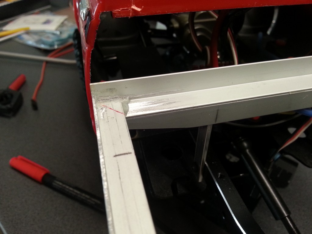
Um aus dem schon gefertigten Grundgerüst nicht gänzlich Aluschrott zu machen, fiel die Entscheidung auf die Verringerung der Breite. So wurde also mit leichtem Versatz aus dem vorderen…
…und hinteren Alu-Winkel jeweils 4 mm ausgesägt. Hier zur Darstellung etwas aufgeweitet.
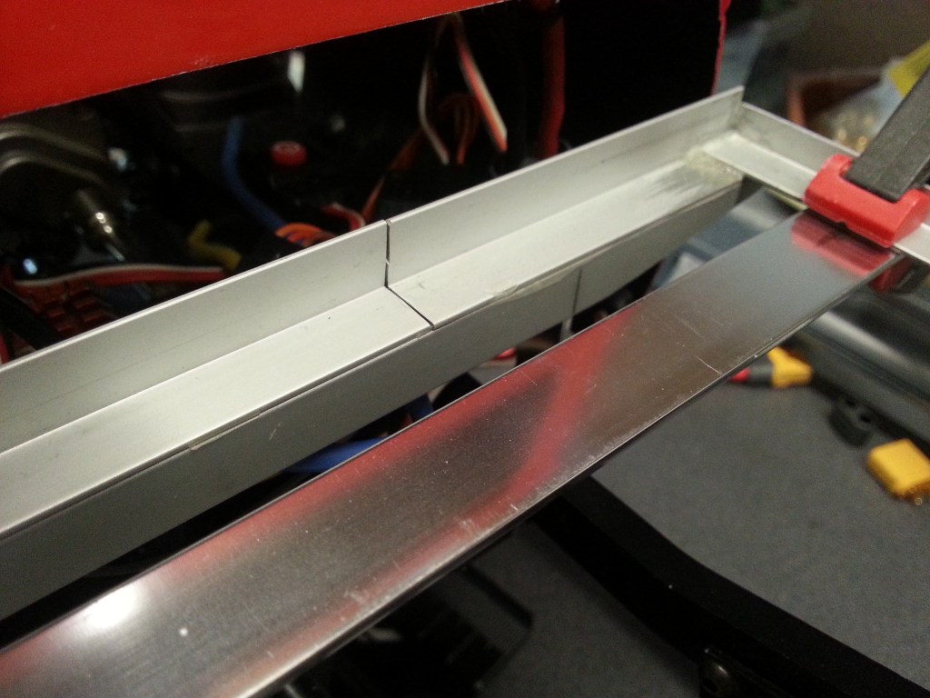
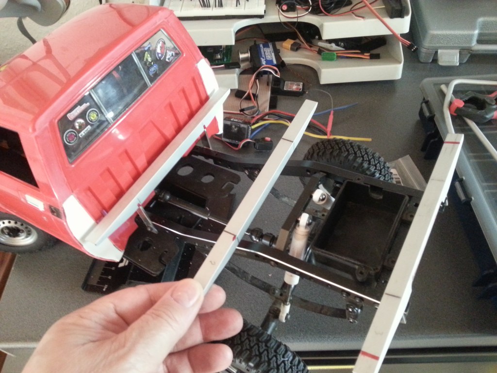
Um wieder ein stabiles Gebilde zu bekommen, wurde im ersten Schritt die vordere Quertraverse mit den beiden Rahmenteilen verklebt. Gleiches wird auch noch hinten und in der Mitte geschehen. Damit die Flucht und der Abstand zum Fahrerhaus exakt sind, war genaues Ausrichten von Nöten. Für das Foto habe ich die hintere Traverse etwas nach links montiert, um die Flucht zum Fahrerhaus zu dokumentieren.
Für sämtliche Verklebungen wurde Uhu Plus endfest verwendet. Über die interaktive Klebeberatung auf der Internetseite von UHU kam ich zu diesem Kleber. Unter Beachtung der Klebevorgaben, anschleifen mit dem beigefügten Schmirgelleinen, entstauben und entfetten, sind bisher alle Klebungen gelungen. Überstehende Klebereste lassen sind nach der mindestens 12-stündigen Aushärtezeit, mechanisch entfernen.
Aus meinen bisherigen Erfahrungen, kann ich hier auch einen Tipp hinterlassen. Über einen gemeinsamen Druckkopf, sollte aus beiden Kanülen jeweils die identische Menge Kleber und Härter gepresst werden. Dies gelingt leider nicht immer in der gleichen Menge. So zumindest die Herstellervorgabe. Daher presse ich vorab eine geringe Menge auf Papier und streiche die Düsen gleichzeitig auch auf dem Papier ab. So wird direkt von Anfang an sichergestellt, dass jeweils 50% Härter und Kleber in die ebenfalls beigefügte Mischschale kommen. Durch kleine Luftblasen und einen ungleichmäßigen Vorschub der beiden Zylinder wird sonst eine ungleichmäßige Mischung erzeugt.
Zwischen dem Schreiben der vorherigen Zeilen und der heutigen Fortsetzung liegen fast 2 Monate. An dieser Stelle wurde mir der Aufwand, die vielen Teile vor dem Kleben zu fixieren, einfach zu groß. Das Untergestell wurde kurzerhand neu gebaut! 😏

Die Quertraversen werden nunmehr verschraubt und daher wurde das Winkelprofil an der Basis, von bisher 10 mm auf 15 mm verändert. Das ursprüngliche Element ist nun also doch Aluschrott…😪
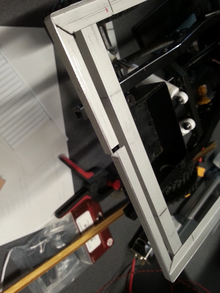
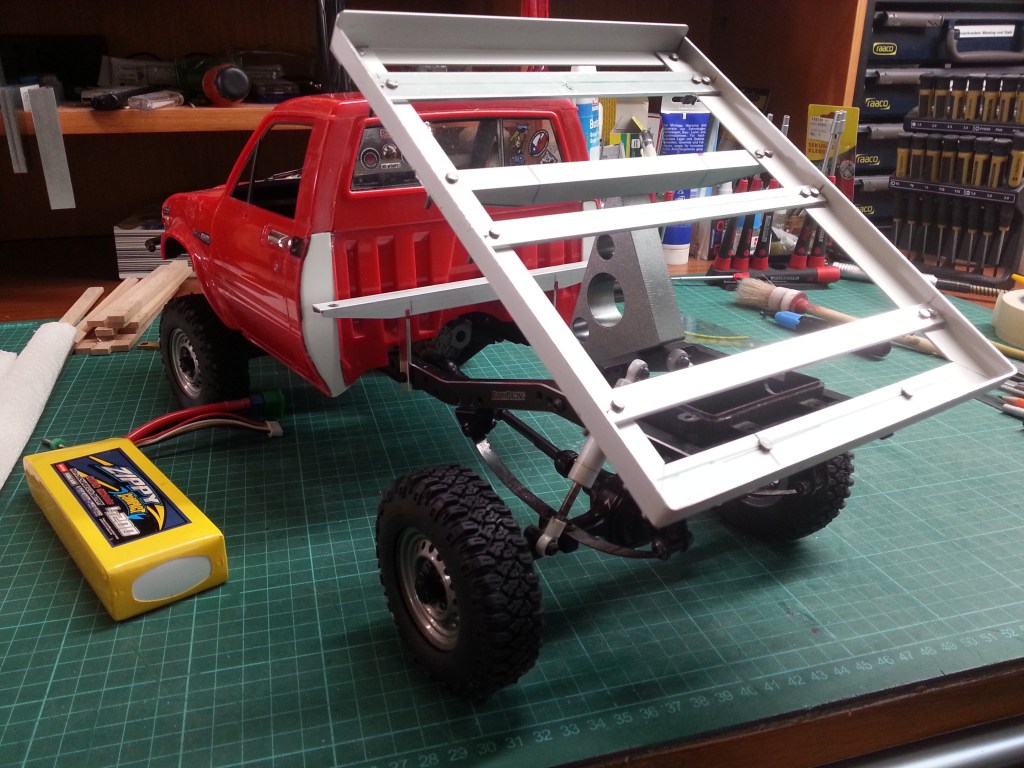
Nach dem Bohren und Verschrauben der Traversen nun das folgende Bild. Erstmals ein stabiles und nun auch in der Breite passendes Bauteil. In Aluminium zu bauen, erfordert etwas mehr Aufwand. Die Innenecken wurden ausgesägt und an der Ecke gebogen. Stahlschrauben M2 verbinden die Teile. Später wird sich durch Feuchtigkeit daran Rost bilden, um die Handwerkskarre realistisch aussehen zu lassen. 😉
Damit der Rand der Ladefläche nicht über die Holzbohlen übersteht, musste auch hier Fräser und Feile zur Höhenkorrektur eingesetzt werden. Das Winkelprofil war leider nicht in der gewünschten Höhe zu bekommen.
Vorne gibt es ein aufgestelltes Profil und bildet so einen erhöhten Abschluss zum Fahrerhaus.
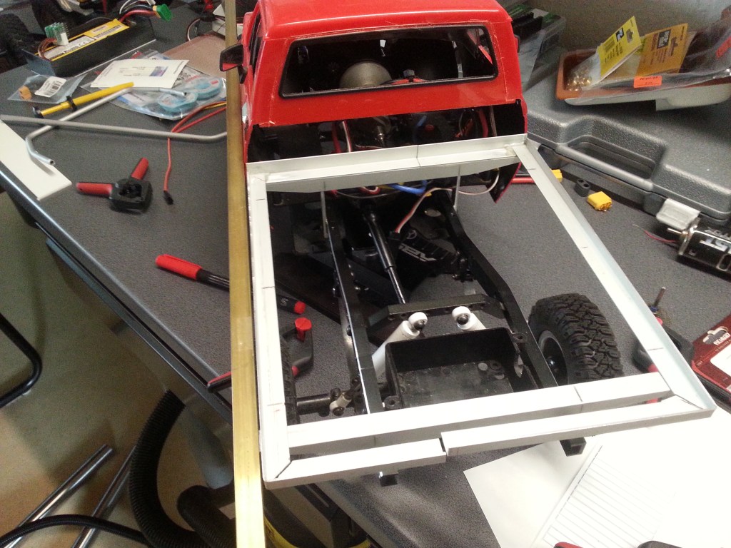
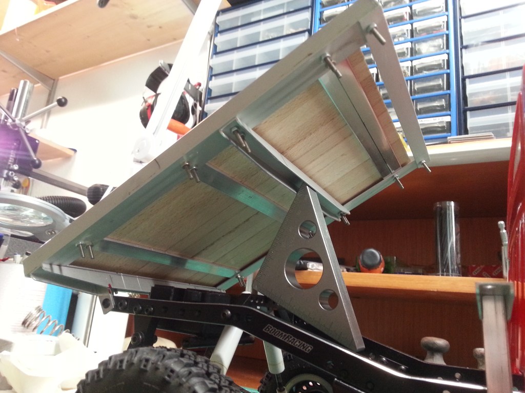
Die Ladefläche an sich wird kippbar, da darunter der Fahrakku (vorne) und die Steuerelektronik (hinten) ihren Platz finden werden. Beide Halterungen aus Flachmaterial werde ich aus Stabilitätsgründen jeweils durch ein U-Profil ersetzen, bzw. eine doppelte Lasche ergänzen.
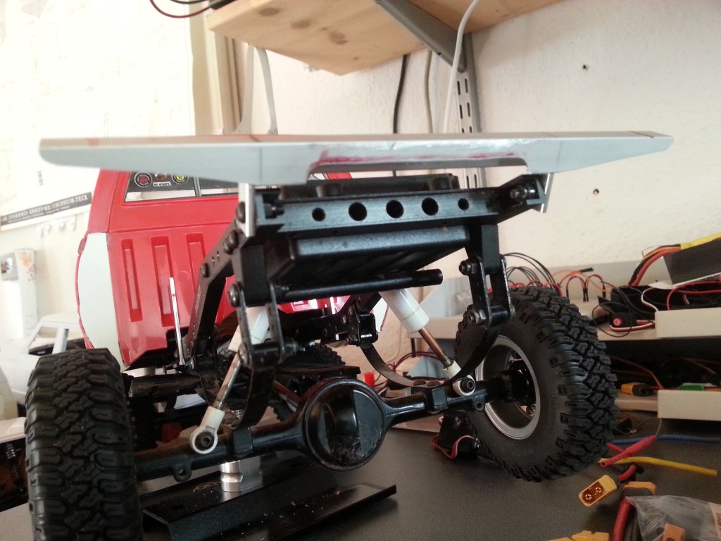
Vorne und in der Mitte liegt die Pritsche auf ihren bisherigen Auflagern.
Vorne und hinten befestigt. Kippen geht jetzt auch! 🙂
Jetzt wieder Holzarbeiten. Vorne gab es noch eine eingepasste Bohle, die mit einer Alustrebe unterbaut wurde. Auf ihr wird der Bügel montiert. Für die Befestigung muss ich mir noch etwas einfallen lassen.

Wegen der überstehenden Mutternköpfe war es nötig, die Bohlen etwas auszusparen. Einmal am vorderen Holz, links und rechts.
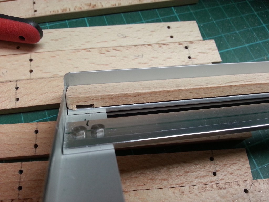
Und ebenso an den beiden seitlichen Bohlen.

Jetzt liegt alles auf einer Ebene und könnte theoretisch befestigt werden. Die Ladefläche wiegt so schon 250 Gramm, die das vorläufige Gesamtgewicht des Toyota auf 3,1 kg bringen. Das gefällt mir und wird das Fahrwerk schön zum Arbeiten bringen. Und noch sind kein Reserverad und die obligatorischen Zusatzteile an Bord.

Zuvor müssen aber noch die Halterungen der Ladefläche fertiggestellt, eine Akkubefestigung gebaut, dass Pritschengestell schwarz lackiert, das Holz gealtert und die Seitenteile mit Heckabschluss montiert sein. Das aber in Kürze! 😃
Wird schnellstmöglich fortgesetzt…
English Version
The Loading platform
In recent weeks, I unfortunately had little desire to tinker. So only small progress has been made. The crisis began with the realization that I was too accurate when measuring the width of the loading area. After adjusting the still provisional side paneling, the error became visible. The elements of the side panels, each 2 mm thick, overlapped the cab by exactly this dimension. So there were three options to choose from. Tolerating the overhang was immediately out of the question. The remaining options were to build a new one or to make the subframe 4 mm narrower.
In order not to make complete aluminum scrap out of the already manufactured base frame, the decision was made to reduce the width. So, with a slight offset, the front…
…and rear aluminum angle 4 mm each. Here a little bit widened for display.
To get a stable structure again, the first step was to glue the front crossbar to the two frame parts. The same will be done at the back and in the middle. So that the alignment and the distance to the driver’s cab are exact, exact alignment was necessary. For the photo, I mounted the rear crossmember slightly to the left to document the alignment to the cab.
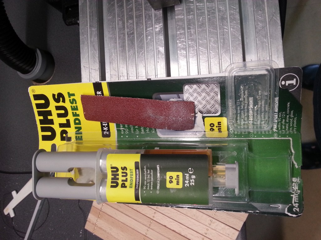
Uhu Plus endfest was used for all bonding. I came to this adhesive via the interactive bonding advice on the UHU website. By following the bonding instructions, sanding with the emery cloth provided, removing dust and degreasing, all bonding has been successful so far. Any excess adhesive residue can be removed mechanically after a curing time of at least 12 hours.
From my experience so far, I can also leave a tip here. The same amount of adhesive and hardener should be pressed out of both cannulas via a common pressure head. Unfortunately, this does not always succeed in the same quantity. At least that is the manufacturer’s specification. That’s why I press a small amount onto paper in advance and also brush the nozzles onto the paper at the same time. This ensures right from the start that 50% each of hardener and adhesive end up in the mixing bowl that is also included. Otherwise, small air bubbles and an uneven feed of the two cylinders will produce an uneven mixture.
There are almost 2 months between the writing of the previous lines and today’s continuation. At this point, the effort to fix the many parts before gluing just became too much for me. The base was rebuilt without further ado! 😏
The crossbars are now screwed and therefore the angle profile at the base, was changed from previously 10 mm to 15 mm. So the original element is now aluminum scrap after all…😪
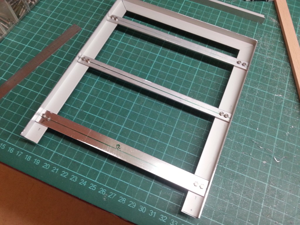
After drilling and screwing the crossbars now the following picture. For the first time a stable and now also in the width fitting component. Building in aluminum requires a little more effort. The inner corners were sawed out and bent at the corner. Steel screws M2 connect the parts. Later, rust will form on it due to moisture, to make the handcart look realistic 😉.
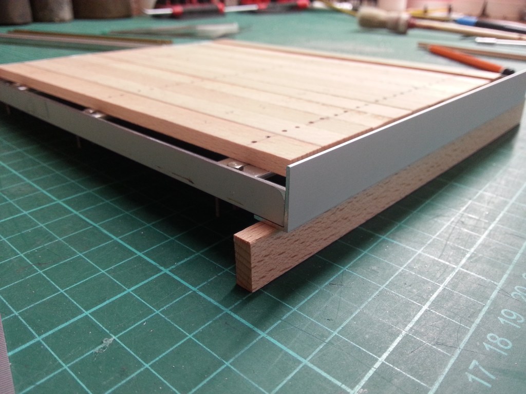
To prevent the edge of the loading area from protruding over the wooden planks, a router and file had to be used to correct the height here as well. Unfortunately, the angle profile could not be obtained at the desired height.
At the front, there is a raised profile, thus forming a raised edge to the driver’s cab.
The loading area itself will be tiltable, because under it the drive battery (front) and the control electronics (rear) will find their place. For stability reasons, I will replace both brackets made of flat material by a U-profile, or I will add a double lug.
In the front and in the middle, the flatbed rests on its previous supports.
Front and rear attached. Tilting is possible now too 🙂 .
Now back to woodwork. In front there was another fitted plank, which was underbuilt with an aluminum strut. On it the bracket will be mounted. I still have to come up with something for the mounting.
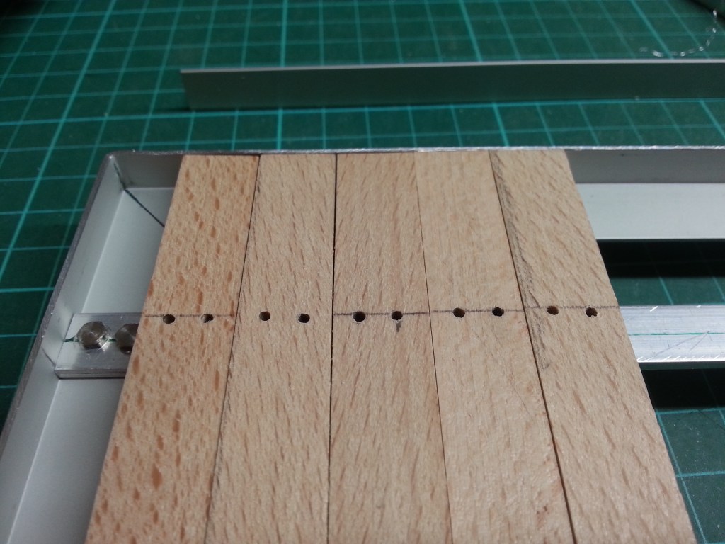
Because of the protruding nut heads, it was necessary to cut out the planks a bit. Once at the front wood, left and right.
And also at the two side planks.
Now everything is on one level and could theoretically be fastened. As it is, the loading area weighs 250 grams, which brings the Toyota’s preliminary total weight to 3.1 kg. I like that and will make the chassis work nicely. And there’s no spare wheel and the obligatory extra parts on board yet.
But before that, the mounts of the cargo area have to be finished, a battery mount has to be built, the flatbed frame has to be painted black, the wood has to be aged and the side panels with rear end have to be mounted. But that will be shortly! 😃
Will be continued as soon as possible…
Translation, with the kind support of deepl.com
