Quellen: Internet-Bildersuche
English Version
Seit dem letzten Beitrag ist einige Zeit vergangen. Nicht das ich mich ausgeruht hätte, große Baufortschritte sind in der Zwischenzeit entstanden. Anlässlich des 100. Beitrages sollte etwas Herausragendes dokumentiert werden. Ich habe ihn dem Truggy gewidmet. Er ist am weitesten fortgeschritten und ich fiebere dem Ende entgegen. Bis dahin ist aber noch viel zu tun. So wollte ich dem Wunsch also Taten folgen lassen.
Bauseitig ist das Fahrerhaus außen schon weitestgehend fertigstellt. Es fehlt u.a. noch das Verschließen der Bohrungen am vorderen Kotflügel, an den Türen war auch noch zu viel Material. So holte ich mir wieder einmal eine stabile Klinge und eben die Karosserie auf die Werkbank. Wichtig, mit der Klingenrückseite die vorgeprägte Fuge, rund um die Seitenfenster, Zug um Zug ausschaben. Zu Beginn mit wenig Druck, damit sich eine winklige Nut ausbildet, in dem die stumpfe Klingenseite danach sauber geführt wird. Das erfordert etwas Geduld, führt aber nach einiger Zeit zum Erfolg. Das Ergebnis sieht täuschend echt aus. Von Versuchen die scharfe Seite zu verwenden möchte ich abraten. Sobald die Schneide nur wenig verkantet, wird sie dieser Richtung folgen und sicher einen tiefen Kratzer verursachen. Genau dort, wo er sicher nicht sein sollte.
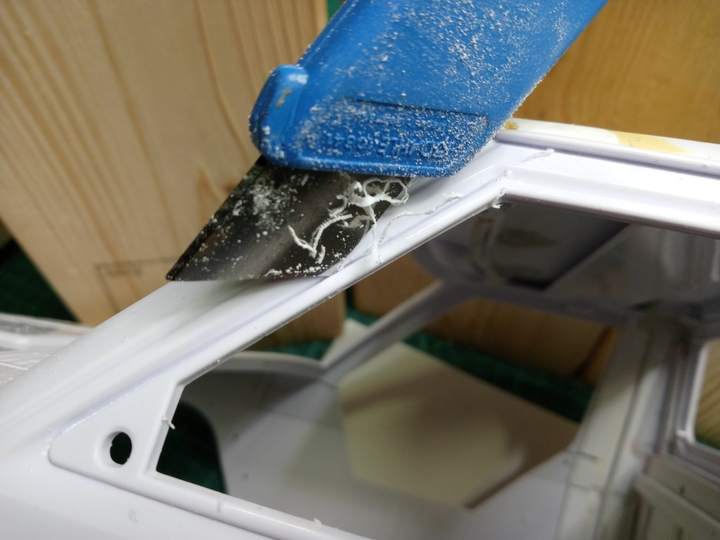
So wird dann irgendwann ein Schatten sichtbar, der das nahende Ende ankündigt.

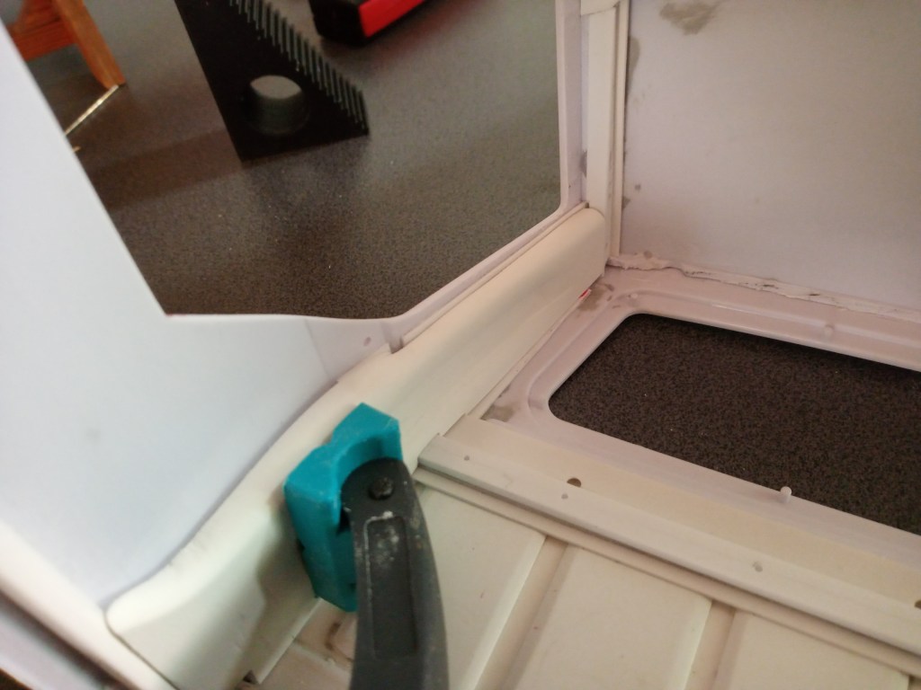
An den Ecken ist das mit etwas mehr Aufwand und Zeit verbunden, da der Arbeitsraum sehr klein geworden ist. Aber ich kann es versprechen, mit Geduld und Disziplin wird es funktionieren. Das Ergebnis sieht dann so aus.
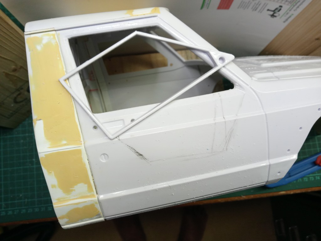
Die Tür musste aber auch unten noch Federn lassen. Dazu war wieder der Dremel mit Trennscheibe am Werk. Nach einer guten Stunde fleißiger Schleifarbeit, ist die Beifahrertür geöffnet.
Die Kontur der Lücke wurde auf eine Papierschablone übertragen und nach einer weiteren Stunde war Durchzug im Fahrerhaus. Dabei habe ich versucht, dass Profil des unteren Fensterrandes wieder einzuarbeiten. Eher etwas für die Optik, aber die soll ja auch einigermaßen stimmen.
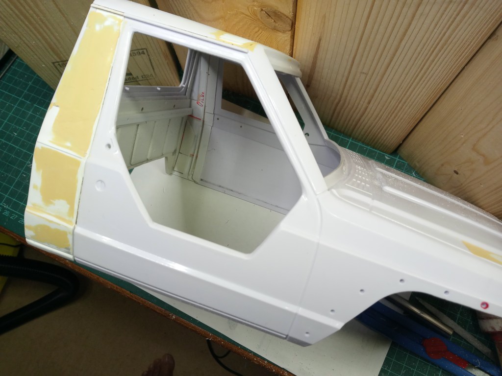
Auch die Fahrertür, nach vorherigem Muster ausgesägt und geschliffen.

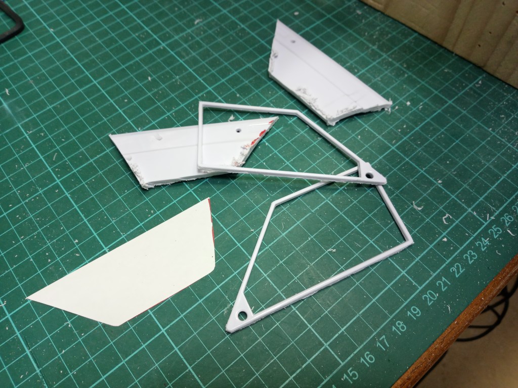
Die Überreste der Trennaktion, ganz links die Papierschablone.
Bevor es mit den anspruchsvollen Bauelementen hinter den Türen weitergeht, der Dachaufbau. Das vorhandene Verstärkungsgerippe wurde komplett entfernt. Die Konturen und sonstigen Überstände abgeschliffen, um eine Basis zu schaffen, die möglichst nahe am Original ist. Nach einiger Schleif- und Anpassungsarbeit, wurde der vordere Abschluss des Dachprofiles zum Dachelement mit einem Z-Profil verschlossen.
So ist es auch am Original!
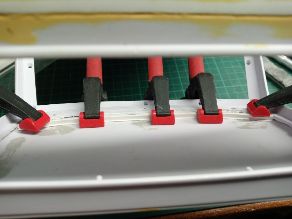
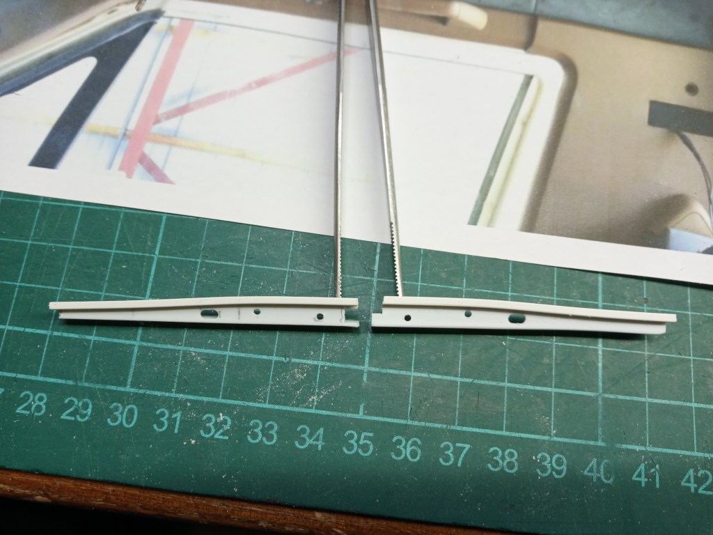
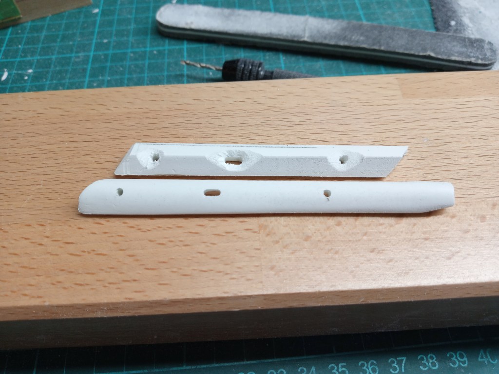
Die seitlichen oberen Abschlüsse zum Dach waren nicht ohne. Aus einem Winkel und einem angeklebten Z-Profil entstand das Detail. Wie im Original mit einem Langloch und zwei Bohrungen. Im nachfolgenden Bild, die linke Seite.

Und beide zusammen. Mangels Foto der linken Seite, habe ich beide einfach spiegelbildlich gebaut. Am hinterlegten Rastermaß von 1 x 1 cm kann man auch die Größe erkennen, ziemlich klein.
Und noch die Gesamteinfassung der Front- und Seitenflächen. Wie im Umfeld gut zu erkennen ist, sind noch einige Teile herzustellen, bis es ein harmonisches Gesamtbild gelungen ist.
Bei der Verkleidung beider A-Säulen war wieder Kreativität und viel Geduld gefragt. Mit einem Drahtstück wurde zunächst der Winkel von Front und Seitenteil ermittelt. Auf dem Koordinatentisch dann zuerst den Winkel und in weiteren Schritten noch Breite und Tiefe passend gefräst. Der Übergang zum Dach dann schrittweise in Handarbeit angepasst. Das war das vorläufige Ergebnis.
Und weiter mit der Handarbeit. Die Kanten wurden schrittweise mit Feile und Schmirgelpapier abgerundet. Das Bauteil einerseits schleifen und dabei auch noch festhalten, ist etwas ganz besonderes. Fingernagelmaniküre inklusive, den groben Teil zumindest. 😊
Zur realistischen Gestaltung wieder einige Durchdringungen. Die meisten davon, wohl Bohrungen für die Befestigung der Innenverkleidung. Damit das Schattenbild auch stimmt, noch Material auf der Rückseite abgetragen. So wirkt das Vollmaterial an den sichtbaren Kanten wie Blechoptik. Das könnte man natürlich auch schwarz malen, oder doch besser gleich richtig…
Dazwischen immer wieder Kontrollen in der A-Säule, ob alles passt. Die nach unten noch überstehenden Stücke werden später mit der Feuerwand zum Motorraum und dem Armaturenbrett angepasst.
Dann war es soweit, nichts geht mehr. Alles verklebt und endgültig fixiert.
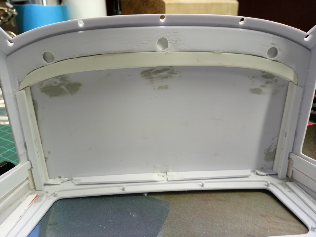
Im Anschluss noch die Blende am Übergang von der Frontscheibe zum Dach. So ist auch diese Unterkonstruktion verkleidet.
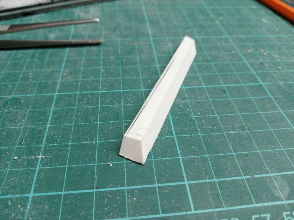
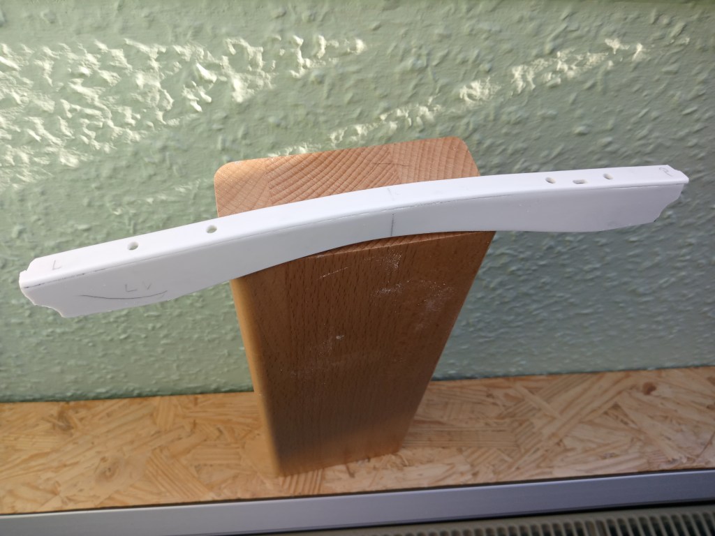
Für das Bodenblech musste noch ein Anschluss an das Fahrerhaus gebaut werden. Dazu wurden unterhalb der Türen, zwei 5 mm breite Viertelstäbe angebracht. Gleichzeitig die Struktur, welche die Rückwand und das Bodenblech verbindet. Eine aufwändige Arbeit, weil nicht alle Bauteile gerade sind, ganz im Gegenteil. Nachfolgend die einzelnen Bauteile und am Bildrand die beiden Viertelstäbe. Das Bodenblech wird von unten verschraubt.

Innerhalb des Profils wurden noch weitere Verstärkungen eingebaut. Das Bodenblech wird aus dünnem PS-Material gebaut und hat somit wenig Stabilität. Es dient alleine der Optik. Einwirkende Kräfte werden also nur direkt an der Karosserie und insbesondere den Ecken abgefangen. Komplett verklebt sieht das Bauteil dann so aus.
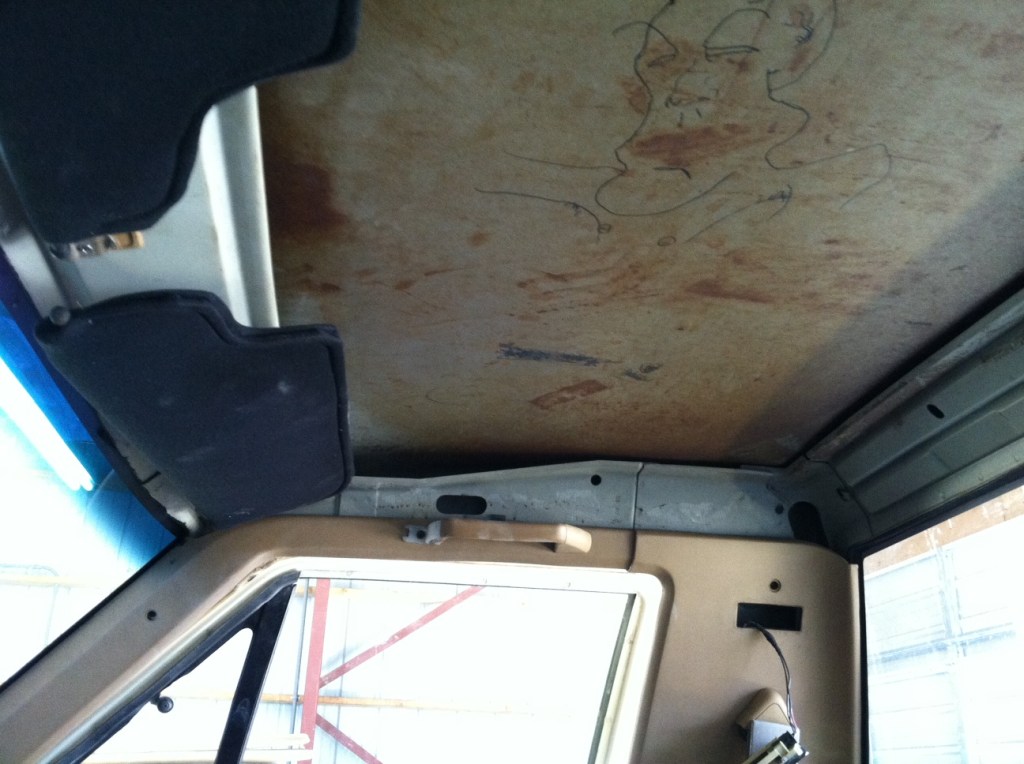
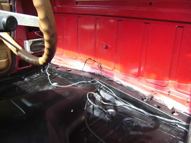
Die Ansicht im Original.
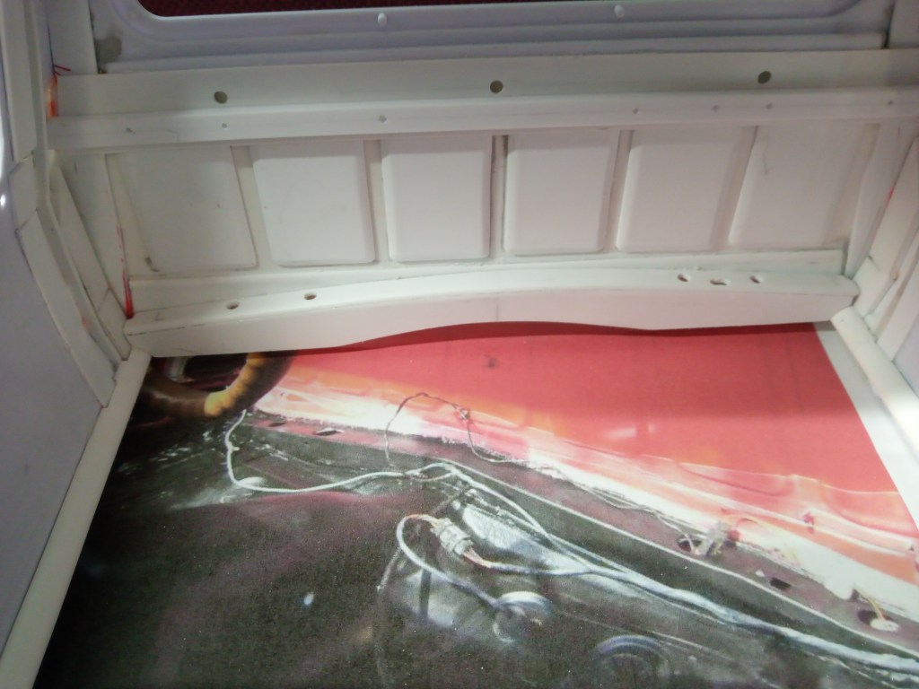
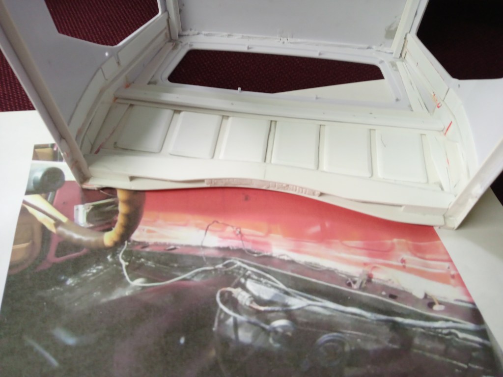
Und hier die Ansicht im Innenraum, bereits auf die Höhe des späteren Bodens angepasst.
Von unten betrachtet, wird auch die Füllung erkennbar. Sie dient der Versteifung des Bauteils.
Auf der Rückseite wurde auch noch die Blechfalz hergestellt, am Übergang von Fahrerhaus und Bodenblech.
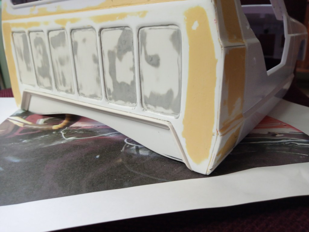
Der absolute Wahnsinn, in fünf Stunden konzentrierter Handarbeit entstand die Blechoptik der rechten hinteren Seitenwand. Sie ist noch nicht fertiggestellt, befindet sich aber schon in einem fortgeschrittenen Bauzustand. Auf der Gegenseite das Ganze noch einmal spiegelbildlich. Ein wirklicher Nervenkitzel. Je länger man schleift und sich die Struktur abbildet, nimmt auch die Gefahr einer Beschädigung zu. Es ist auf die Kontur des Fahrerhauses angepasst und hat verschiedene Wandstärken. Auch die Einprägung in der Mitte ist diffizil. Schnell ist man beim Schleifen über das Ziel hinausgeschossen. Die nachfolgende Bilderschau zeigt den Werdegang. Am Fußteil wird schliesslich noch eine großflächige Aussparung eingearbeitet.
Auch das Profil für die Fahrerseite wurde in mehrstündiger Handarbeit hergestellt. Das gestaltete sich etwas einfacher, weil schon eine Vorlage zur Verfügung stand. So war ich eine halbe Stunde früher fertig…

Eine kleine Winkelleiste schaffte noch einen optischen Abschluss der Fahrerhausrückwand zum Heckfenster.

In der Gesamtansicht, der Innenraum mit allen bisher gebauten Teilen.
Im folgenden Beitrag geht es u.a. mit der inneren Struktur der Türen weiter. Die habe ich mir bis zum Schluss aufgehoben. Sie werden in den verbliebenen Bereich eingepasst. Zusätzlich noch der Dachabschluß, oberhalb des Heckfensters und weiteren optische Maßnahmen.
Wird schnellstmöglich fortgesetzt…
English Version
The Truggy cab, inside and out
Sources: Internet image search
Since the last post some time has passed. Not that I have rested, great construction progress has been made in the meantime. On the occasion of the 100th contribution something outstanding should be documented. I dedicated it to the Truggy. It is the most advanced and I am eagerly awaiting the end. But there is still a lot to do until then. So I wanted to follow the wish with action.
On the construction side, the exterior of the driver’s cab is already largely finished. The holes at the front wing still need to be closed and there was still too much material at the doors. So once again I got a sturdy blade and the body on the workbench. It is important to scrape out the pre-stamped joint around the side windows with the back of the blade. Apply a little pressure at the beginning so that an angular groove is formed, then guide the blunt side of the blade cleanly. This requires a little patience, but after a while it will be successful. The result looks deceptively real. I would advise against trying to use the sharp side. As soon as the edge tilts just a little, it will follow this direction and surely cause a deep scratch. Exactly where it should not be.
So at some point a shadow will become visible, announcing the approaching end.
At the corners this requires a little more effort and time, as the working space has become very small. But I can promise you, with patience and discipline it will work. The result will look like this.
The door also had to be sprung at the bottom. Again, the Dremel with cutting disc was at work. After a good hour of hard work, the passenger door is open.
The contour of the gap was transferred to a paper template and after another hour there was draught in the cab. I tried to incorporate the profile of the lower window edge again. Rather something for the optics, but that should be also to some extent correct.
Also the driver’s door, sawed out and sanded according to the previous pattern.
The remains of the cutting action, on the far left the paper template.
Before continuing with the demanding construction elements behind the doors, the roof structure. The existing reinforcing framework was completely removed. The contours and other protrusions were sanded down to create a base that is as close as possible to the original. After some sanding and adjustment work, the front end of the roof profile to the roof element was closed with a Z-profile.
This is how it is on the original!
The upper side closures to the roof were not without difficulty. The detail was created from an angle and a glued-on Z-profile. As in the original with one oblong hole and two drillings. In the following picture, the left side.
And both together. Due to the lack of a photo of the left side, I simply built both as mirror images. You can see the size from the 1 x 1 cm grid, it’s quite small.
And still the total bordering of the front and side surfaces. As you can see in the surroundings, there are still some parts to be made until a harmonious overall picture is achieved.
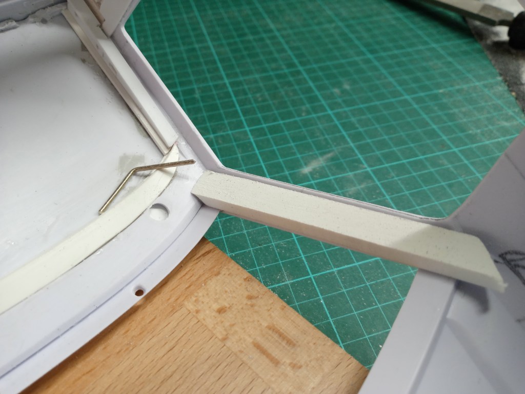
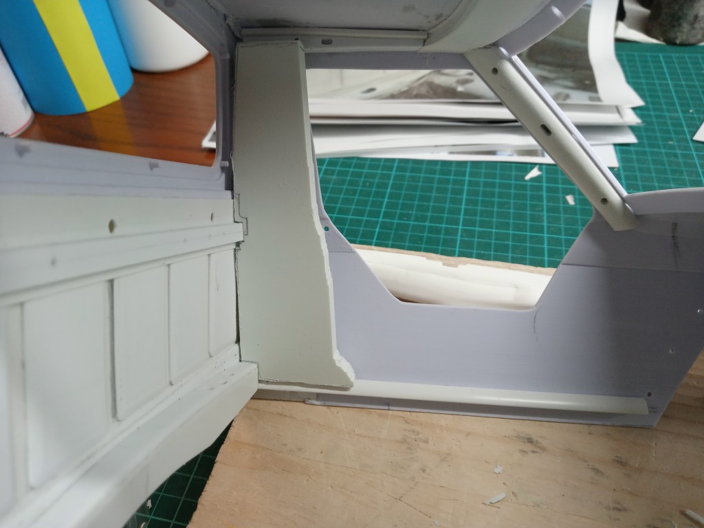
For the cladding of both A-pillars, creativity and a lot of patience were again required. First, the angle of the front and side parts was determined with a piece of wire. On the coordinate table, the angle was first milled and then, in further steps, the width and depth were milled to fit. The transition to the roof was then adjusted step by step by hand. That was the preliminary result.
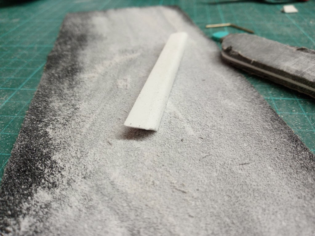
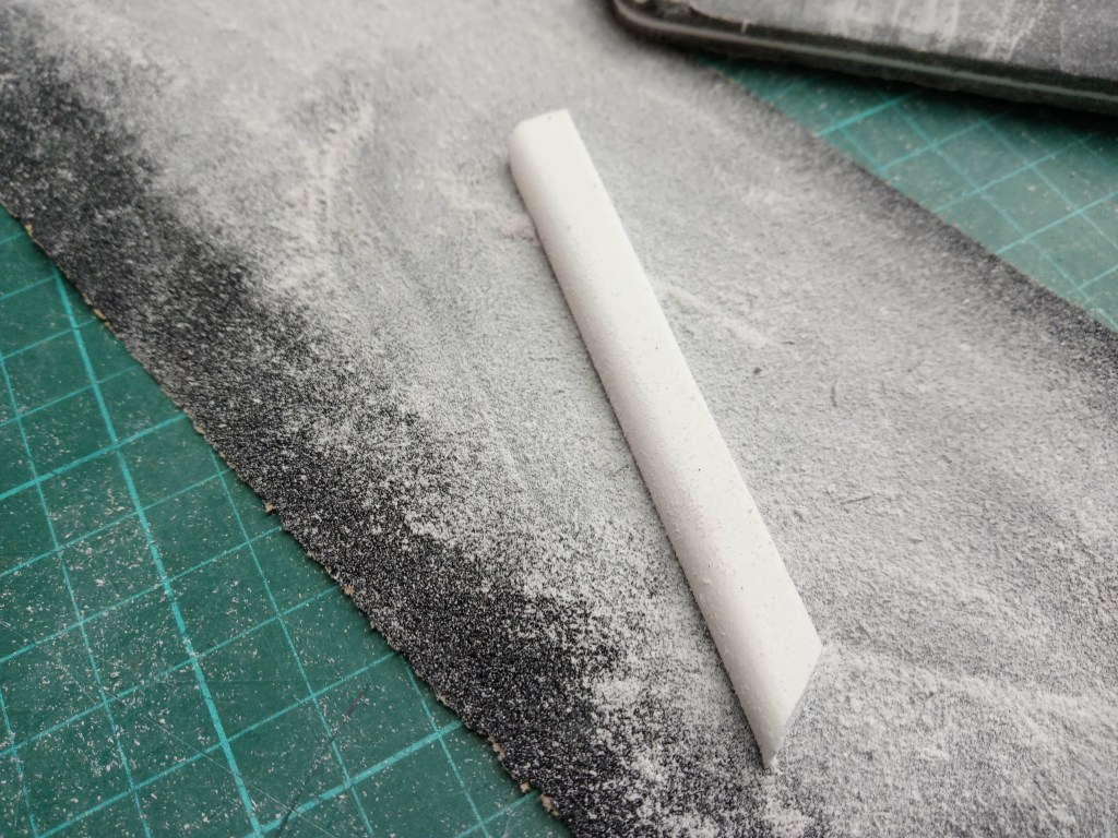
And on with the manual work. The edges were gradually rounded off with a file and sandpaper. Sanding the part on the one hand and holding it on the other hand is something very special. Fingernail manicure included, the rough part at least. 😊
For realistic design, again some penetrations. Most of them, probably holes for fixing the interior panelling. To make the shadows look right, some material was removed from the back. This makes the solid material look like sheet metal at the visible edges. Of course, you could also paint it black, or better yet, do it properly…
In between, the A-pillar is checked again and again to see if everything fits. The pieces still protruding downwards will later be fitted with the firewall to the engine compartment and the dashboard.
Then it was time, nothing more goes. Everything is glued and finally fixed.
After that, the panel at the transition from the windshield to the roof. So this substructure is also covered.
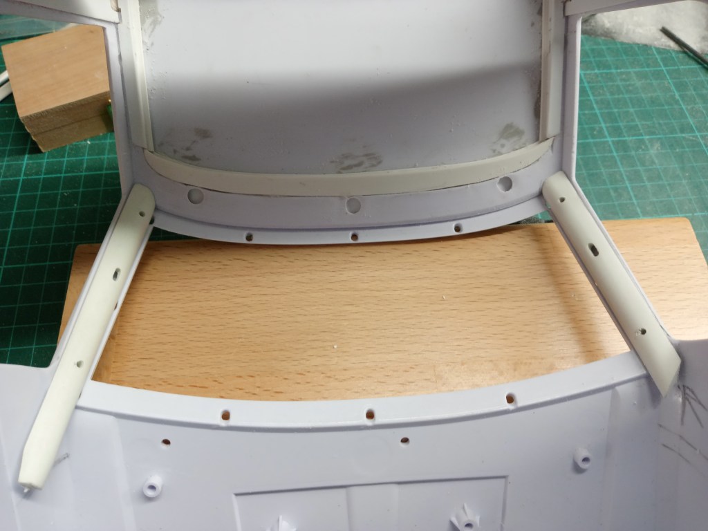
For the floor panel, a connection to the driver’s cab had to be built. For this purpose, two 5 mm wide quarter rods were attached below the doors. At the same time, the structure that connects the rear wall and the floor panel. This was a complicated job, because not all components are straight, quite the opposite. Below are the individual components and, at the edge of the picture, the two quarter rods. The bottom panel is screwed on from below.
Further reinforcements were installed within the profile. The bottom plate is made of thin PS material and therefore has little stability. It is used solely for visual purposes. Forces acting on it are therefore only absorbed directly at the bodywork and especially at the corners. Completely glued, the component looks like this.
The original view.
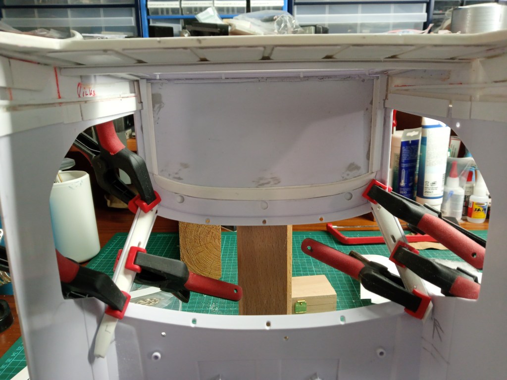
And here the view in the interior, already adjusted to the height of the later floor.
Viewed from below, the filling is also visible. It serves to stiffen the component.
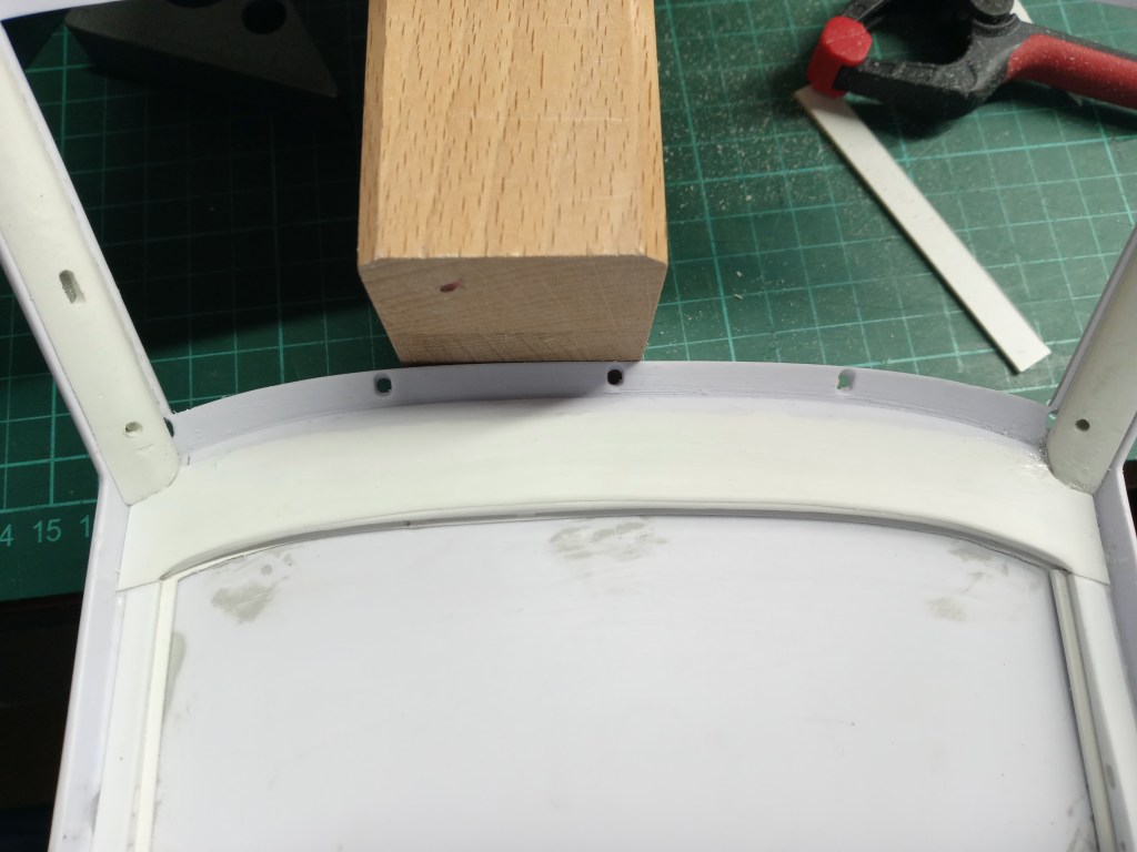
On the rear side, the sheet metal seam was also produced, at the transition between the driver’s cab and the floor panel.
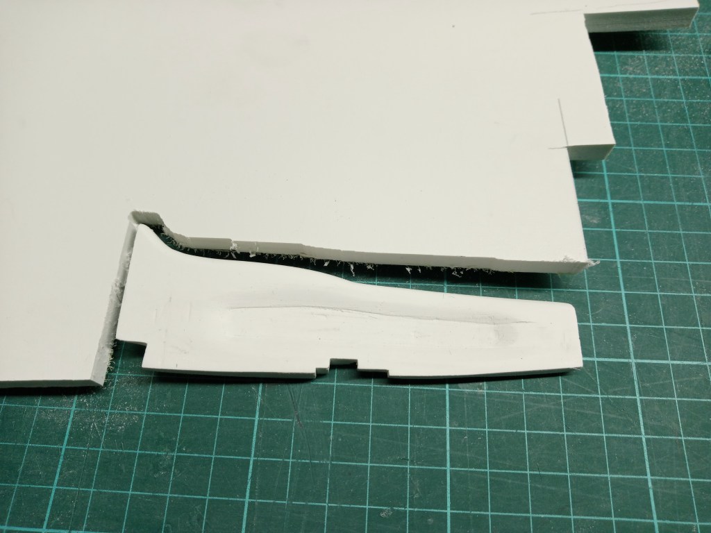
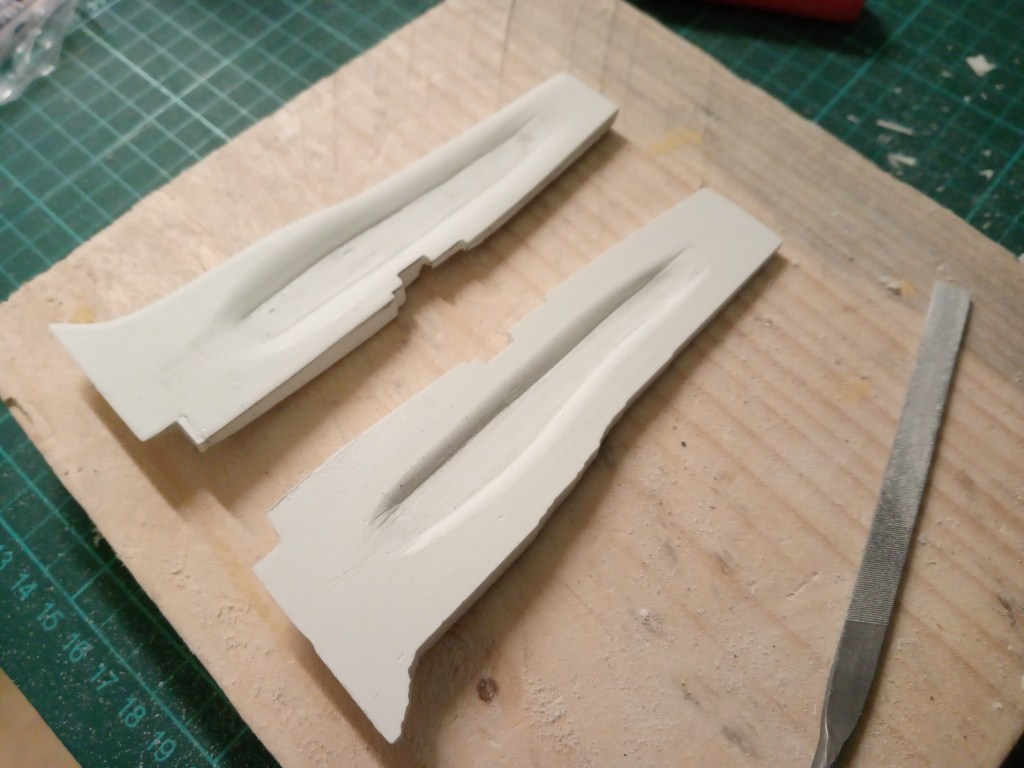
Absolute madness, in five hours of concentrated manual work, the sheet metal look of the right rear side wall was created. It is not yet finished, but is already in an advanced state of construction. On the opposite side, the whole thing is mirrored once again. A real thrill. The longer you sand and the more the structure appears, the greater the risk of damage. It is adapted to the contour of the side wall and has different wall thicknesses. The embossing in the middle is also tricky. It is easy to overshoot the mark when sanding. The following picture shows the process. Finally, a large recess is made in the foot part.
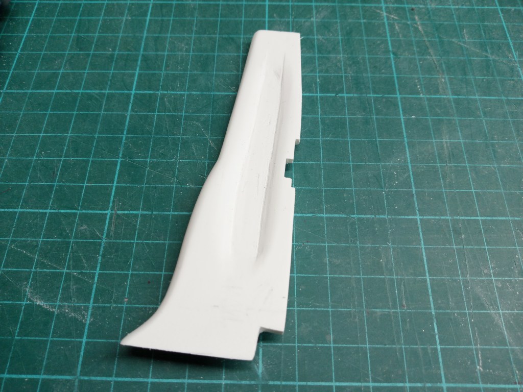
The profile for the driver’s side was also made by hand in several hours of work. This was a little easier because a template was already available. So I was finished half an hour earlier…
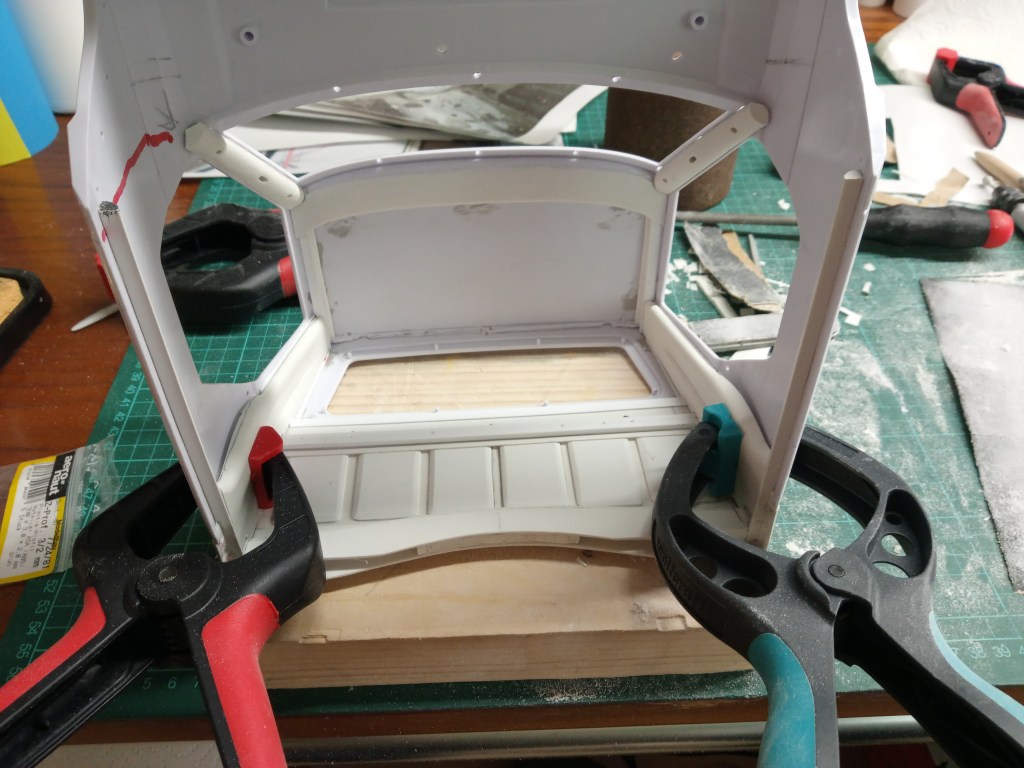
A small angle strip creates a visual border between the rear wall of the cab and the rear window.
In the general view, the interior with all built parts.
The following article continues with the inner structure of the doors, among other things. I have saved these for last. They will be fitted into the remaining area. In addition, there is the roof closure above the rear window and other optical measures.
Will be continued as soon as possible…
Translation, with the kind support of deepl.com
