Quellen: Bauer Modelle
English Version
Mein Wunsch den Truggy in diesem Frühjahr fertig zu bekommen, ist etwas gedämpft worden. Schuld daran ist das Modellschiff Marina. Es macht mir gerade so viel Spaß daran zu basteln, dass anderes in den Hintergrund treten musste.
Gerade hat Bauer-Modelle wieder meine Bestellung ausgeliefert. Ein kleiner Familienbetrieb mit Vergangenheit und so auch sicher für die Zukunft gerüstet. Eine eigene Konstruktionsabteilung gehört zum Portfolio, hier nachzulesen. Es wäre einmal interessant zu wissen, ob Herr Bauer seinerzeit auch als Graupner Konstrukteur für die Marina zuständig war. Wie auch immer, ein guter Tipp für jeden Schiffs-Modellbauer!
Die kleine Marina, so einfach wie sie auch aufgebaut ist, macht echten Spaß. Schon weil ich sie gerne aus dem tristen Dasein erlösen möchte. In neuen Glanz und mit etwas gehobener Ausstattung. Das erste sichtbare Detail sitzt präsent auf dem Fahrstand, ein neuer Mast. Diese Baustelle fing recht gut an und forderte mein ganzes Können und Durchhaltevermögen. Glück ist natürlich auch dabei und das stand mir bisher auch bei, sollte mich aber bitte nicht aus den Augen verlieren. 😏
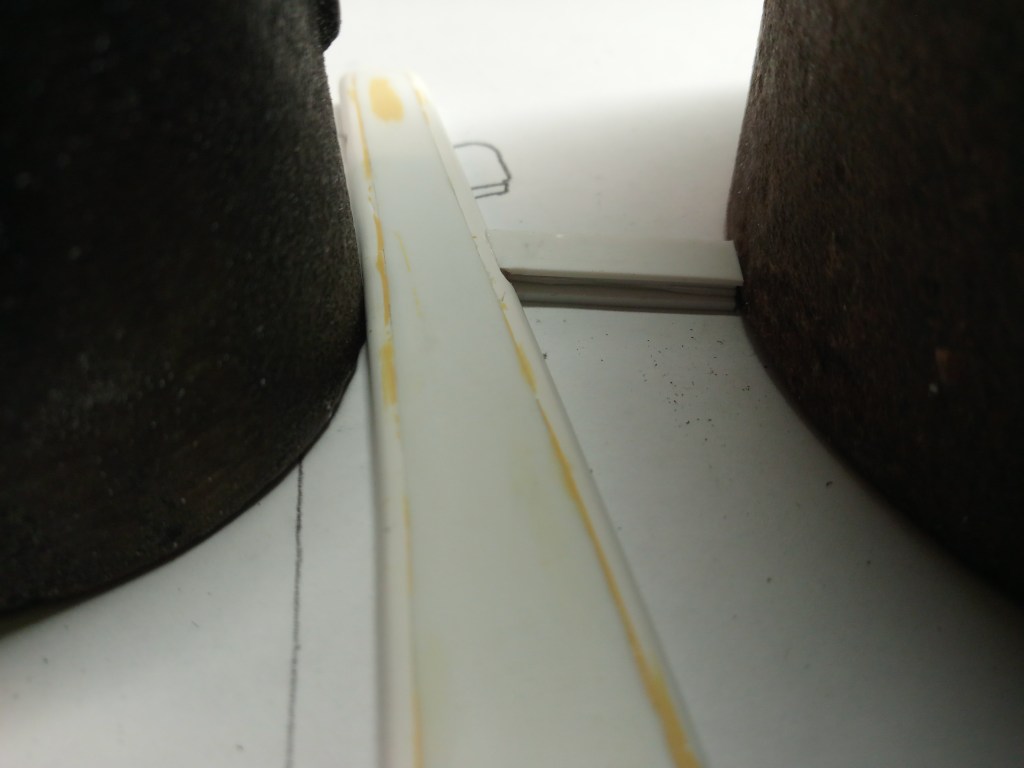
Zum Schluss meines letzten Beitrages, hatte ich zwei mikroskopische Dreiecke gezeigt, auf denen einmal die Mastlampen positioniert werden sollten. Zu winzig im Detail und mit maximaler Herausforderung beim Bauen. Daher nun zum Werdegang meiner weiteren Idee. Es begann wie schon so oft. Zwei Plattenreste wurden aufeinander geklebt und anschließend an den langen Außenseiten winklig abgefräst. Wie kam ich früher nur ohne meinen Koordinatentisch zurecht? 😄
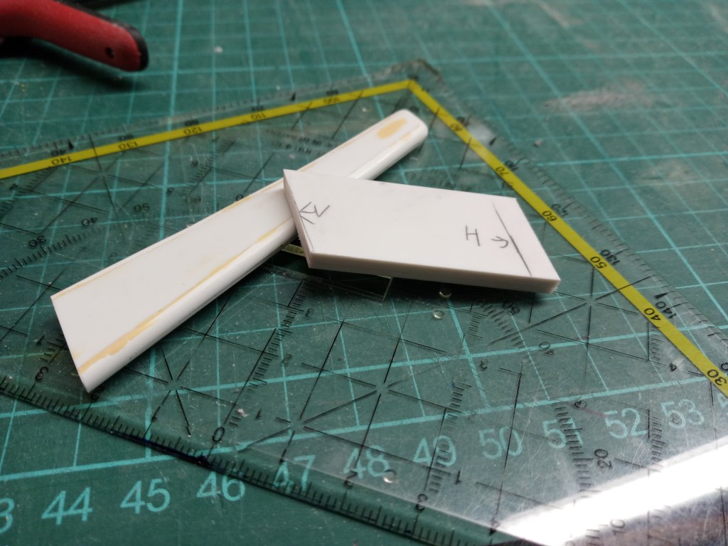
Im nun folgenden Schritt, wurde das Bauteil auf die spätere Höhe des Auslegers angepasst. So sieht man auch erstmals, in welche Richtung die Baustelle führen soll.
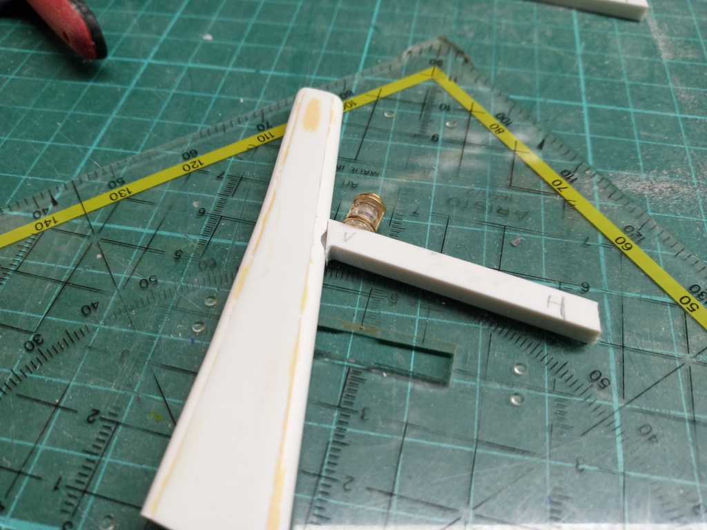
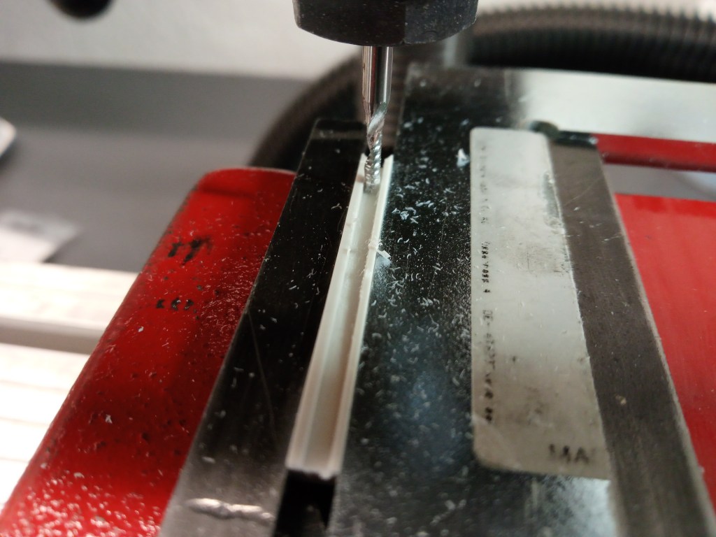
Damit sich das Bauteil auch an die Rundung und Neigung des Mastes anpassen konnte, wieder etwas fräsen und feilen.
Und da waren ja auch noch Kabel, die es zu versteckt galt. Eine Nut für die Kabel an der Unterseite, die ich eigentlich besser oben angebracht hätte. Man lernt beim Bauen immer noch dazu. Dazu später noch mehr Informationen.
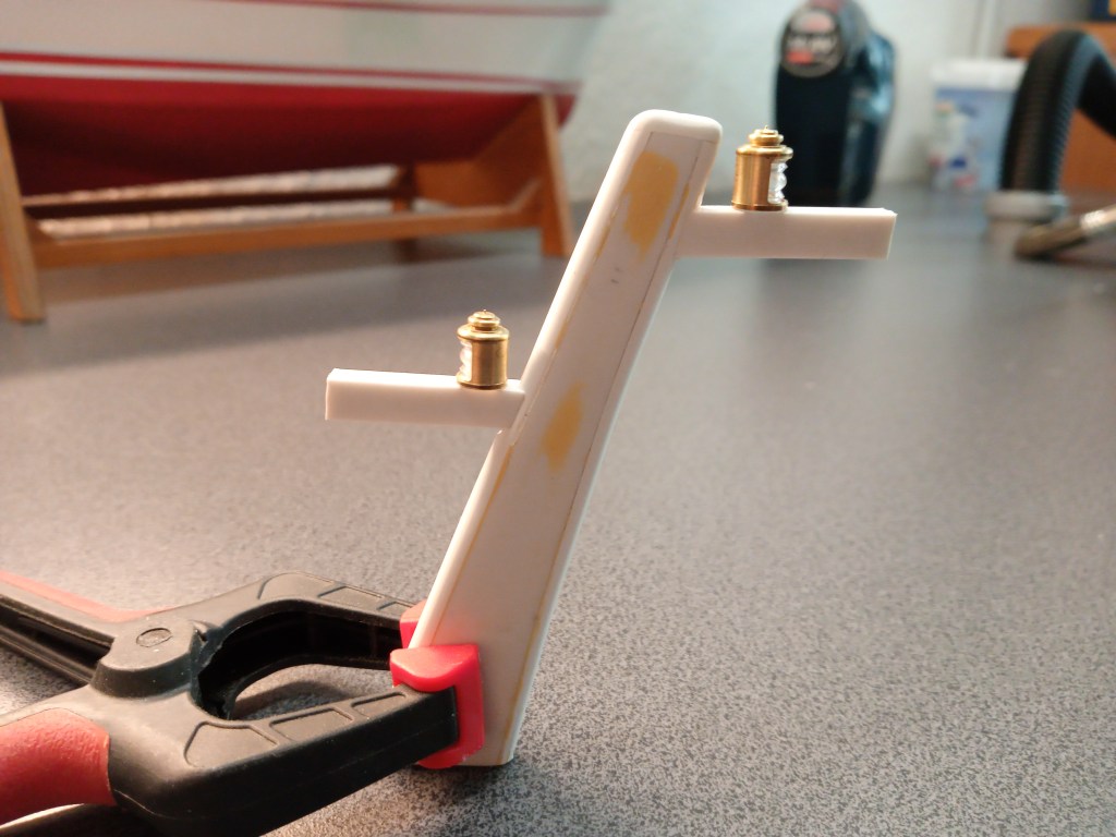
Der vordere Lampenträger schon etwas gekürzt und für die Klebung fixiert.
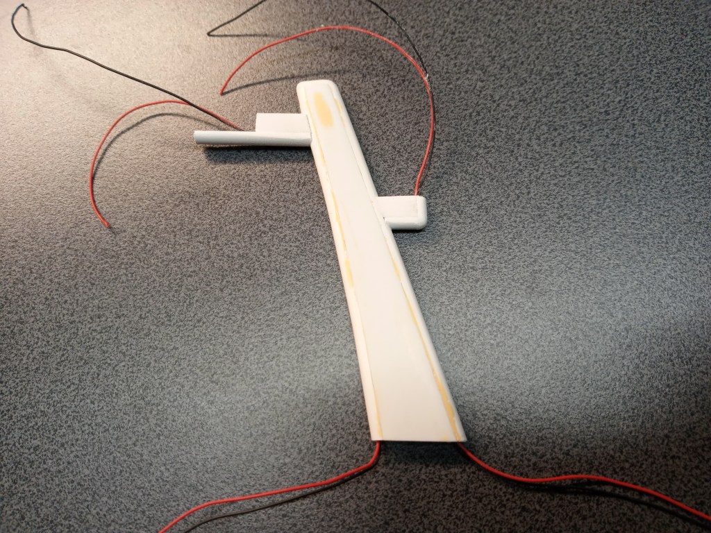
Nachdem auch die Gegenseite einen Lampenfuß erhalten hatte, die erste Ansicht auf das vorläufige Ergebnis.
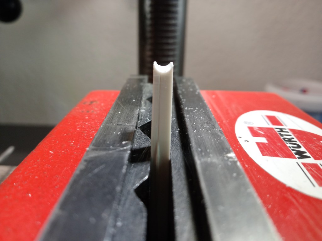
Soweit zum einfachen Teil der Minibaustelle. Schon ganz gut, aber noch völlig unförmig und unproportioniert. Um diese Ziel zu erreichen, wurde ein U-Profil etwas eingefräst. Ein guter Ansatz, wie ich im Nachhinein und auch zu meinem Glück eingestehen muss. Nachfolgend also das untere U-Profil, mit Ausformung der Mastkontur. Auf der nicht sichtbaren Rückseite, die zusätzliche Nut für das Kabel.
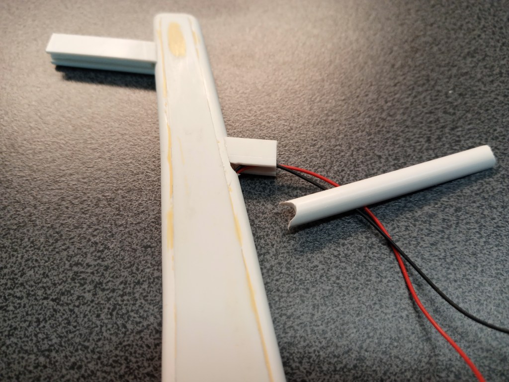
Nach Verklebung des unteren und vorderen Profils, rechts das fertige Ergebnis und links der vorbeschriebene Zwischenschritt. Anhand des Bildes kann man sich nun auch die verwinkelte Kabelführung vorstellen. Rechts im Profil führt das Kabel bis zur Bohrung Richtung Ausleger. An dessen Unterseite wieder nach rechts und dann nach oben. Durch meine großzügige Gestaltung der Kanäle lässt sich so das Kabelpaar mit Wiederstand noch bewegen. Hätte ich die das Kabel im Ausleger oben verlegt, wäre mir die letzte unnötige Richtungsänderung erspart geblieben. Theorie und Praxis führen nicht immer zum gleichen Ergebnis.
Der nächste Schritt bestand im Bau der elektrischen Anlage. Da die zur Verfügung stehende Spannung deutlich über der für LEDs zulässigen Spannung liegt, müssen Widerstände vorgeschaltet werden. Da die Widerstände nicht in den kleinen Lampengehäusen unterzubringen sind, habe ich mir dazu eine zentrale und übersichtliche Variante überlegt. Eine kleine Platine mit Ein- und Ausgangsseitigen Lötstiften und dazwischen den verlöteten Widerständen. Auf die Lötstifte kommt ein sogenannte Buchsenleiste, der die benötigten Ein- und Ausgänge flexibel verbindet. Gesteuert wird alles über das Schaltmodul eines Forumskollegen, die ich schon in einem früheren Beitrag vorgestellt hatte. Schematisch sieht das Schaltbild dann so aus:
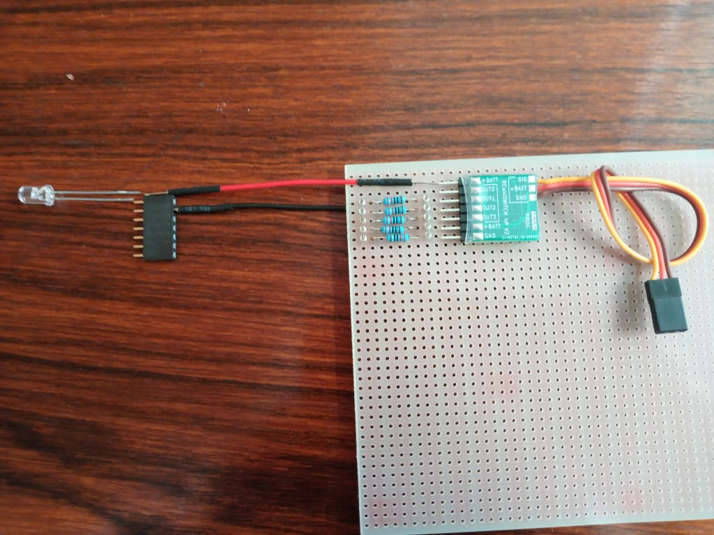
Aus dem Schaltmodul wird Plus (+) aus dem Empfänger direkt mit der Anode verbunden. Die Anode entspricht also dem Pluspol. Optisch am längeren Anschlussdraht erkennbar. Als Kathode wird bei einer LED der Minuspol (-) bezeichnet, die zudem auch kürzer als die Anode ist.
Die Ausgänge Out0, Out1, und Out2 sind die möglichen Schaltausgänge für LEDs. Sie schalten jeweils die Kathode, also Minus (-). An den Ausgängen Out3, +Batt und GND wäre in dieser Ausführung der direkte Anschluss eines Servos möglich. Im verlinkten Beitrag wird auch das Modul RCuniSwitch LED vorgestellt. Es hat am Ausgang Out3 eine zusätzliche Anschlussmöglichkeit für LEDs. Das Modul ist individuell programmierbar und ideal für Anfänger. Das große Anwendungsspektrum begeistert aber auch die Profis.
Zum Schluss noch die wichtigste aller Fragen.
Ist es gelungen?
Nachfolgend die Antwort… 😍
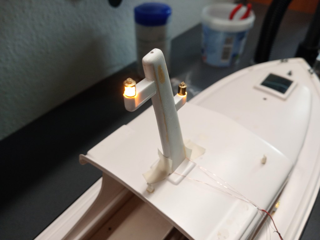
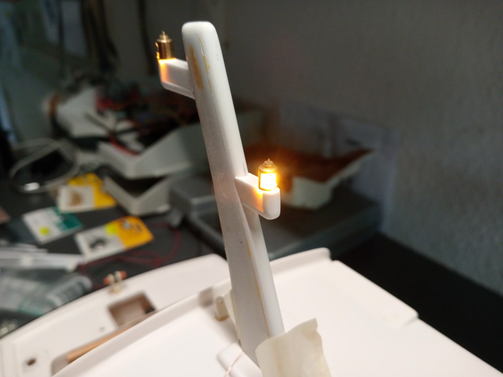
Für die Beleuchtung habe ich mich letztlich noch zum Einsatz von SMD-LEDs mit angelötetem Kupferlackdraht entschieden. Die sind so dünn, dass sie an den verlegten Kabeln angelötet und eingezogen werden konnten. Sie sind am unteren Ende des Mastes erkennbar.
Damit das Licht nicht nach unten durchleuchtet, wird hier auch noch „abgedunkelt“. Jetzt noch das Radom und die Mastbefestigung bauen, den letzten Nass-Feinschliff, dann kann hier grundiert und lackiert werden.
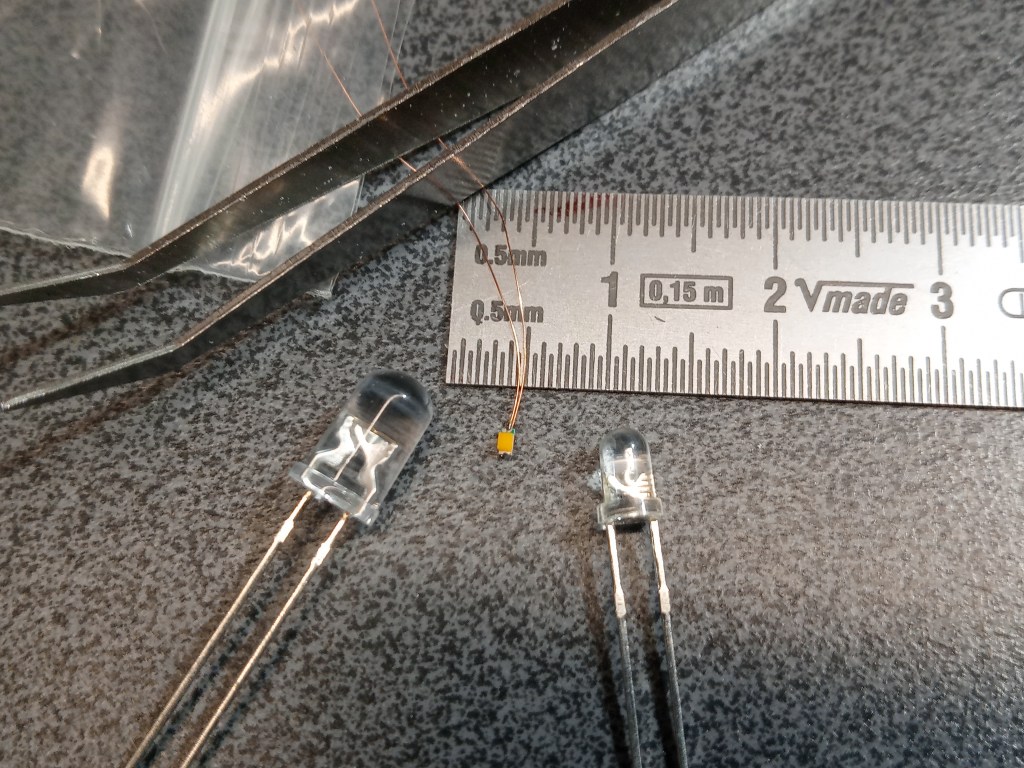
Zum Abschluss noch ein Größenvergleich der SMD LED (Mitte) mit Standard 3 und 5 mm LEDs.
Wird schnellstmöglich fortgesetzt…
English Version
The Marina does not let me go yet…
Sources: Bauer Modelle
My desire to get the truggy done this spring has been somewhat dampened. The Marina model ship is to blame. I’m having so much fun building it that other things have had to take a back seat.
Bauer-Modelle has just delivered my order again. It’s a small family business with a long history, so it’s well equipped for the future. An own construction department is part of the portfolio, you can read here. It would be interesting to know if Mr. Bauer was also responsible for the Marina as a Graupner designer at that time. Anyway, a good tip for every ship model builder!
The little Marina, as simple as it is built, is real fun. If only because I would like to redeem it from its dreary existence. In new splendor and with a little more upscale equipment. The first visible detail sits present on the driving stand, a new mast. This construction site started quite well and demanded all my skills and stamina. Luck is of course also involved and that stood by me so far, but please should not lose sight of me. 😏
At the end of my last post, I had shown two microscopic triangles on which once the mast lamps should be positioned. Too tiny in detail and with maximum challenge in building. Therefore now to the development of my further idea. It began as so often before. Two plate remnants were glued on top of each other and then milled off at an angle on the long outer sides. How did I get along before without my coordinate table? 😄
In the now following step, the component was adjusted to the later height of the boom. So you can also see for the first time in which direction the construction site should lead.
So that the component could also adapt to the curvature and inclination of the mast, again some milling and filing.
And there were also cables that needed to be hidden. A groove for the cables at the bottom, which I actually would have better placed at the top. One always learns while building. More information about this later.
The front lamp holder already shortened a bit and fixed for gluing.
After the opposite side had also received a lamp base, the first view on the preliminary result.
So much for the easy part of the mini construction site. Already quite good, but still completely shapeless and disproportionate. To achieve this goal, a U-profile was milled in a bit. A good approach, as I must admit in retrospect and also to my good fortune. The following is the lower U-profile, with the mast contour formed. On the not visible back side, the additional groove for the cable.
After gluing the lower and front profile, on the right the finished result and on the left the intermediate step described above. Based on the picture, you can now also imagine the angled cable routing. On the right side of the profile, the cable leads to the hole in the direction of the boom. At its bottom side it goes to the right again and then upwards. Due to my generous design of the channels, the cable pair can still be moved with resistance. If I had routed the cable in the boom at the top, I would have been spared the last unnecessary change of direction. Theory and practice do not always lead to the same result.
The next step was to build the electrical system. Since the available voltage is significantly higher than the permissible voltage for LEDs, resistors have to be connected upstream. Since the resistors cannot be accommodated in the small lamp housings, I thought of a central and clear variant for this. A small circuit board with solder pins on the input and output side and the soldered resistors in between. On the solder pins comes a so-called socket strip, which flexibly connects the required inputs and outputs. Everything is controlled by the switching module of a forum colleague, which I had already presented in an earlier post. Schematically the circuit diagram looks like this:
From the switching module, plus (+) from the receiver is connected directly to the anode. The anode corresponds to the positive pole. Visually recognizable by the longer connecting wire. The cathode of an LED is the negative pole (-), which is also shorter than the anode.
The outputs Out0, Out1, and Out2 are the possible switching outputs for LEDs. They each switch the cathode, i.e. minus (-). At the outputs Out3, +Batt and GND the direct connection of a servo would be possible in this design. In the linked article also the module RCuniSwitch LED is presented. It has an additional connection possibility for LEDs at output Out3. The module is individually programmable and ideal for beginners. However, the wide range of applications also inspires professionals.
Finally, the most important of all questions.
Did it succeed?
Below is the answer… 😍
For the lighting I finally decided to use SMD LEDs with soldered enamelled copper wire. They are thin enough that they could be soldered to the routed cables and pulled in. They can be seen at the bottom of the mast.
So that the light does not shine through to the bottom, it is also „darkened“ here. Now build the radome and the mast mounting, the last wet fine sanding, then can be primed and painted here.
Finally, a size comparison of the SMD LED (center) with standard 3 and 5 mm LEDs.
Will be continued as soon as possible…
Translation, with the kind support of deepl.com
