Quellen: RC4WD, Architekturversand.de
English Version
Ein Bild mit kleinen M2-Schrauben hatte ich schon einmal vorgestellt. Deren Optik war aber alles andere als maßstabsgerecht.
Daher hatte ich eine Auswahl an RC4WD-Mikroschrauben gekauft. Die Schrauben haben einen Bund und einen 6-kant-Kopf, mit einer Schlüsselweite von 2 mm. Erhältlich mit verschiedenen Durchmessern, Längen und Farbe.
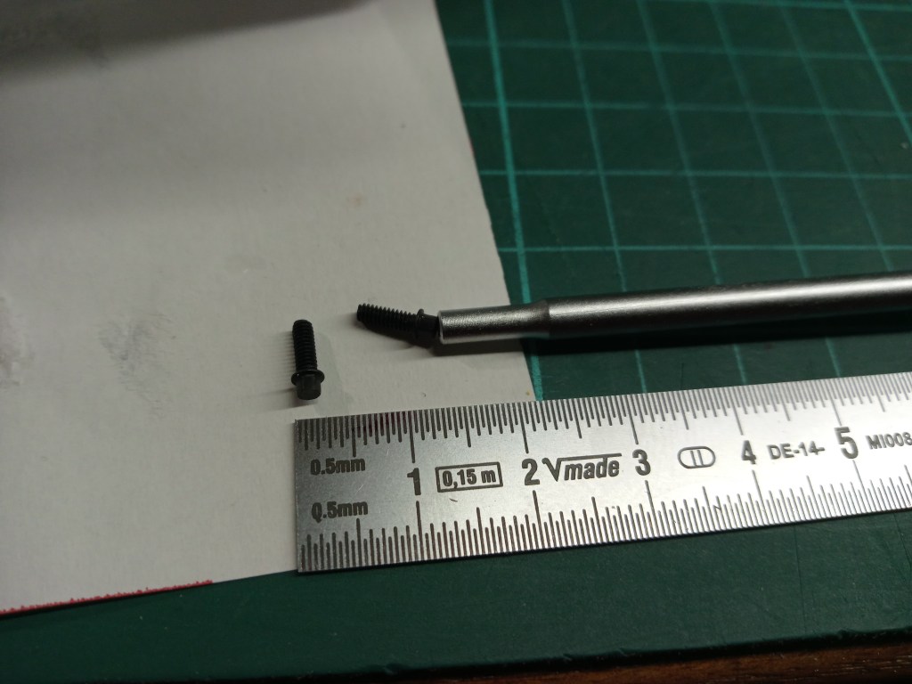
Da der erste Versuch nicht so exakt war, wie gewünscht, musste ich einen Versuch starten. Meine Vorstellung; das Gewinde auf 1,5 mm aufbohren und einen PS-Stift mit identischem Durchmesser einkleben. Im nachfolgenden Foto schon eingeklebt, aber noch ungekürzt.
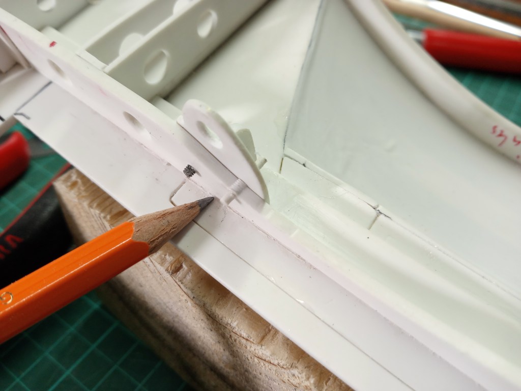
Mit dem Cuttermesser bündig abgetrennt und einem neu positioniertem M2-Gewinde, dass nachfolgende Ergebnis.
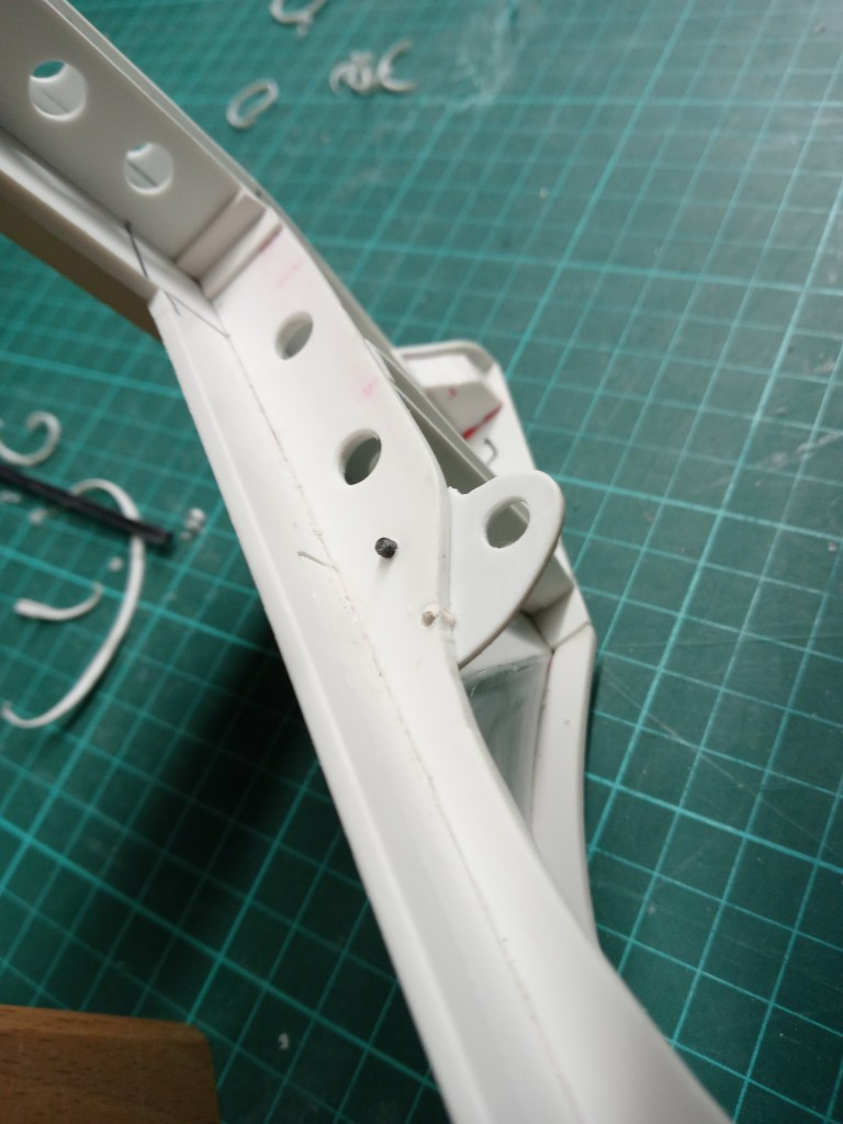

Nun sieht das Ergebnis sauber aus, die Schlüsselweite ist realitätsnah, ich wieder um einige Euros ärmer, aber zufrieden. Da auch die bisher verbauten M3-Schraube verbannt wurden, gleich nach der identischen Methode das vorhandene Loch auf 5 mm aufgebohrt und ebenfalls verschlossen. Da ich noch weitere Löcher zu schließen hatte, war die letzte Bestellung bei meinem Lieferanten Architekturversand auch etwas umfangreicher. Polystyrolstangen mit Durchmessern von 1,5 – 5,0 mm.
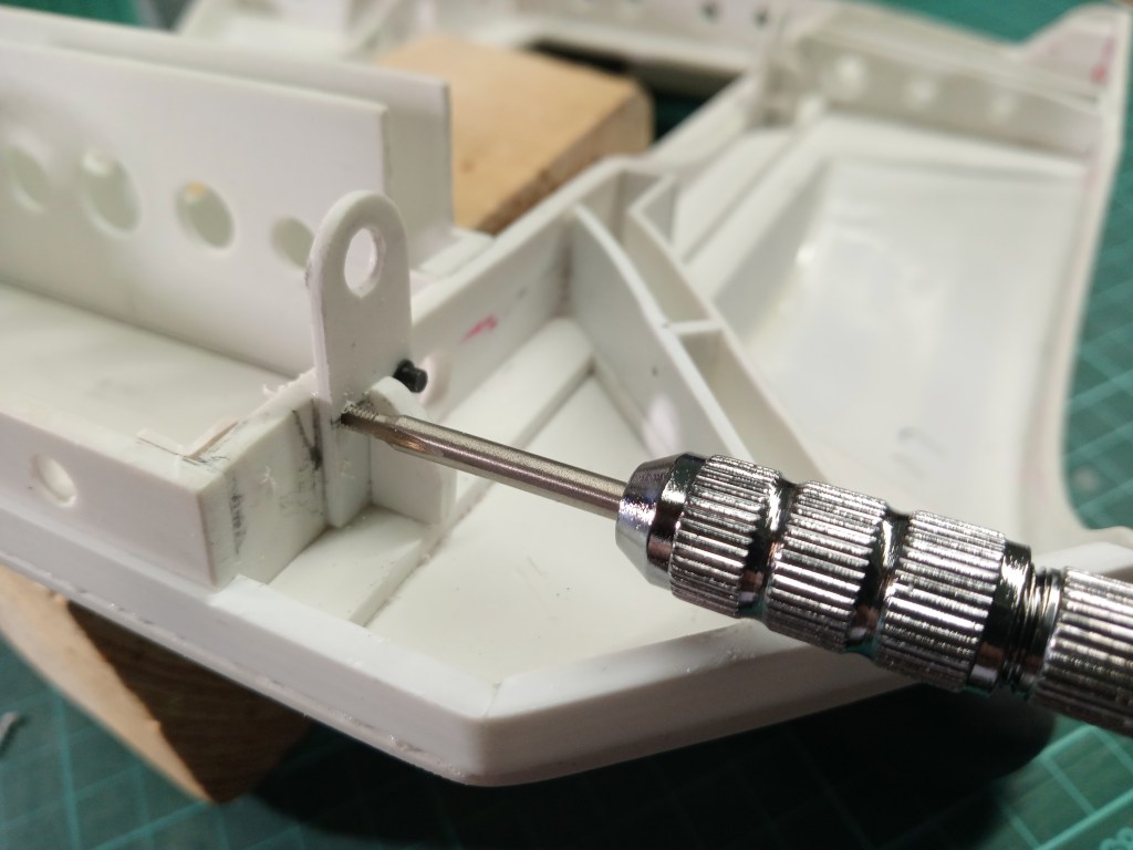
Der Werdegang; mit einem 1,6 mm Bohrer ein Kernloch vorbohren und mittels feinem Spannhalter das M2-Gewinde einschneiden.
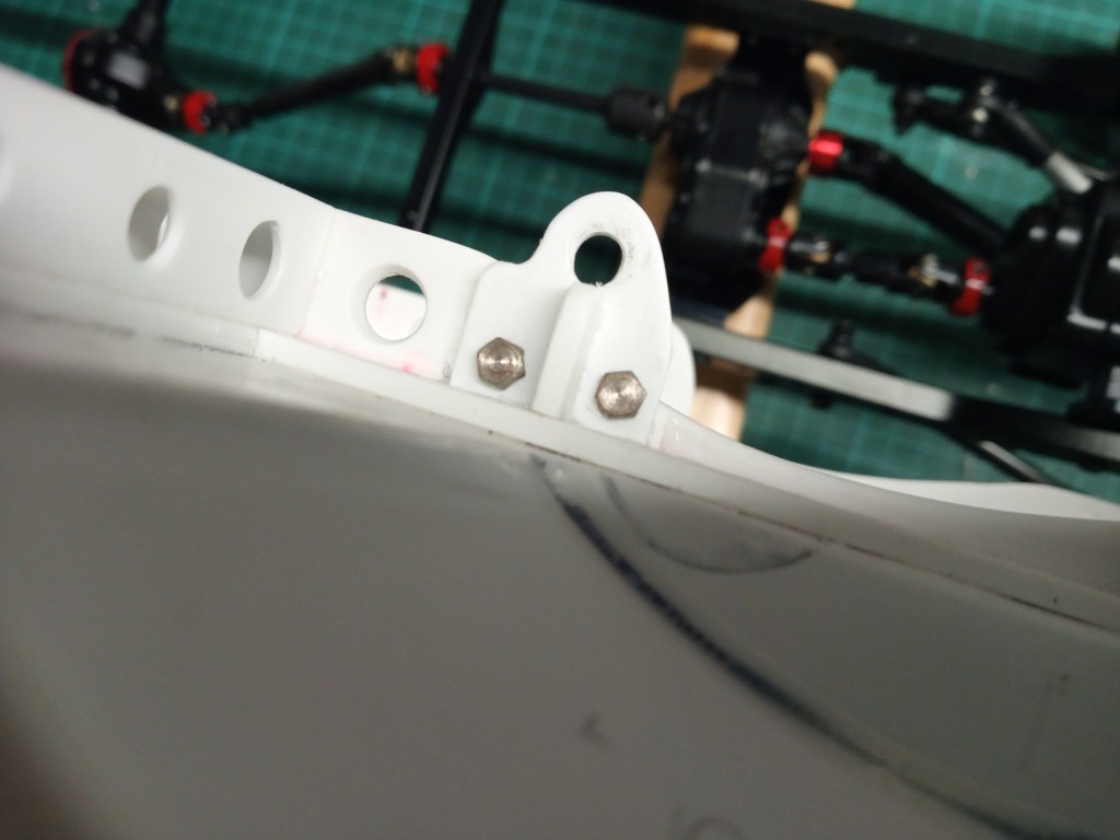
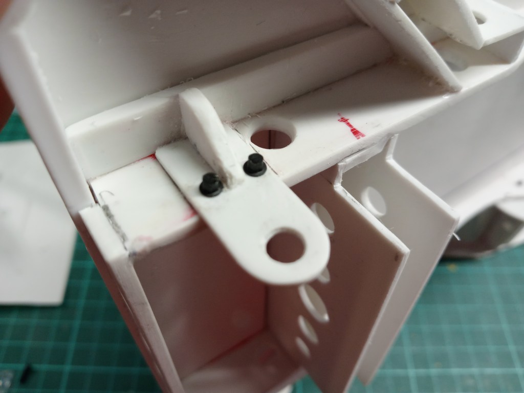
Die Optik der Microschrauben spricht für sich. Echte Haltefunktionen haben diese Schrauben allerdings nicht. Der eigentliche Halter ist mit dem Hilfsrahmen verklebt.
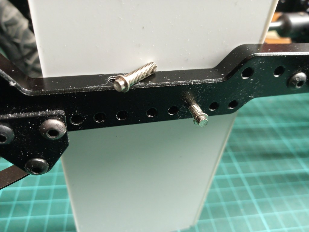
Nach dem bündig schleifen aller 5 mm Öffnungen, wird die Ladefläche u.a. mit 3,0 mm Microschrauben am Rahmen befestigt. Schlüsselweite 2,5 mm entsprächen im Original einer Schlüsselweite von ca. 21 mm. Das ist eine realistische Größe. Im Vergleich dazu die benachbarten Originalschrauben. Deren Austausch ist aber nicht vorgesehen. Nach längerer Nutzung in Schmutz und mit Oxidation, werden die kleinen Schraubenköpfe wohl nicht in der Lage sein, die dann notwendigen Kräfte übertragen zu können. Daher werden auch ggf. vorhandene Gewinde im Rahmen ausgebohrt und rückseitig eine Mutter montiert.
Dann noch einige Stunden Feinarbeit für den vorderen Ladeflächenhalter. Zuerst wurden zwei PS-Stücke miteinander verschraubt. So lassen sich gleich zwei Teile in einem Vorgang anfertigen.
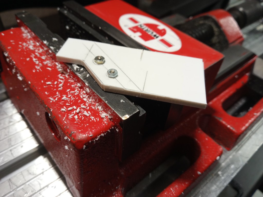
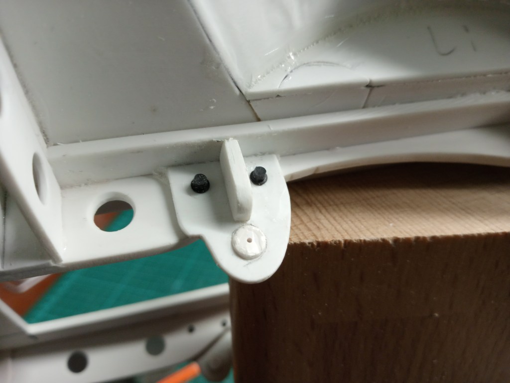
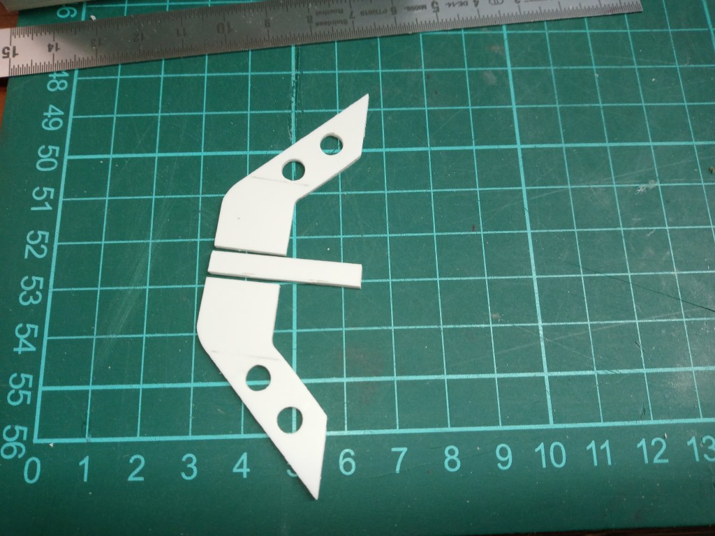
Nach dem Ausschneiden noch Bohrungen für die Optik. Jeder Halter besteht aus insgesamt fünf Bauteilen. Die beiden Hauptbestandteile im nachfolgenden Bild. In der Mitte der noch ungekürzte Abstandstreifen, um die beiden Stützelemente im vorhandenen U-Profil zu fixieren.
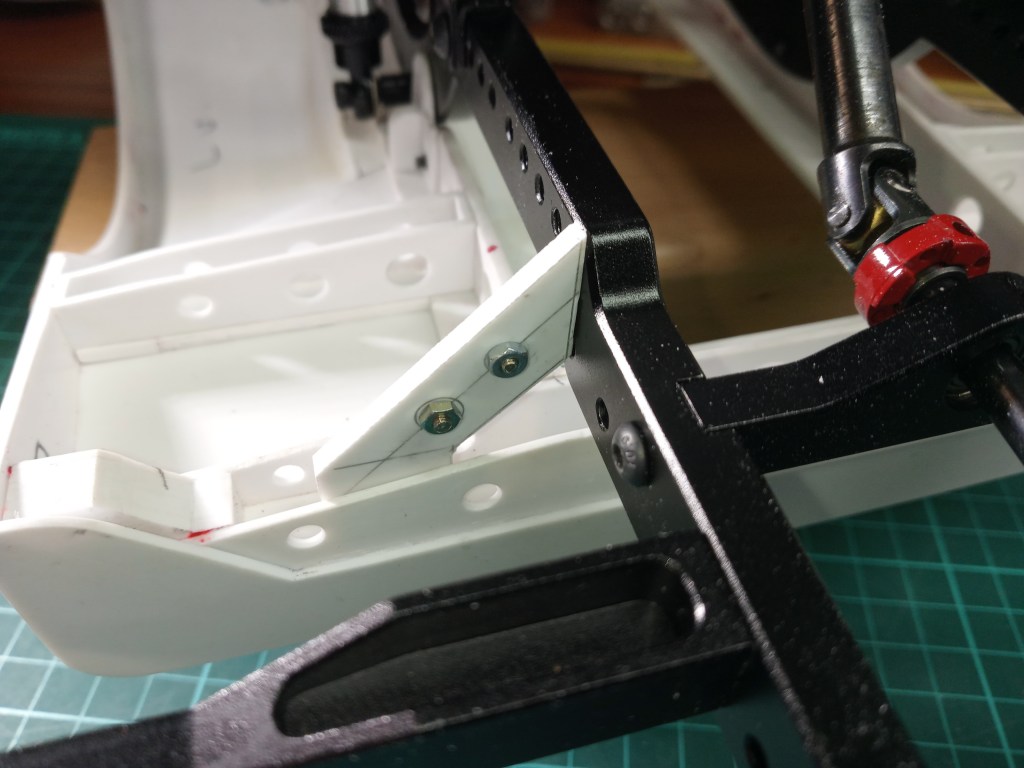
Ein weiteres Bauteil wurde noch zur Verschraubung mit dem Rahmen benötigt. Die noch benötigte Bohrung ist hier aber noch nicht vorhanden.
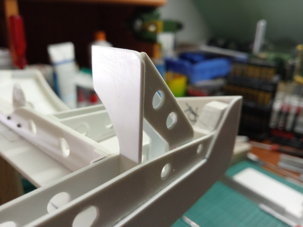

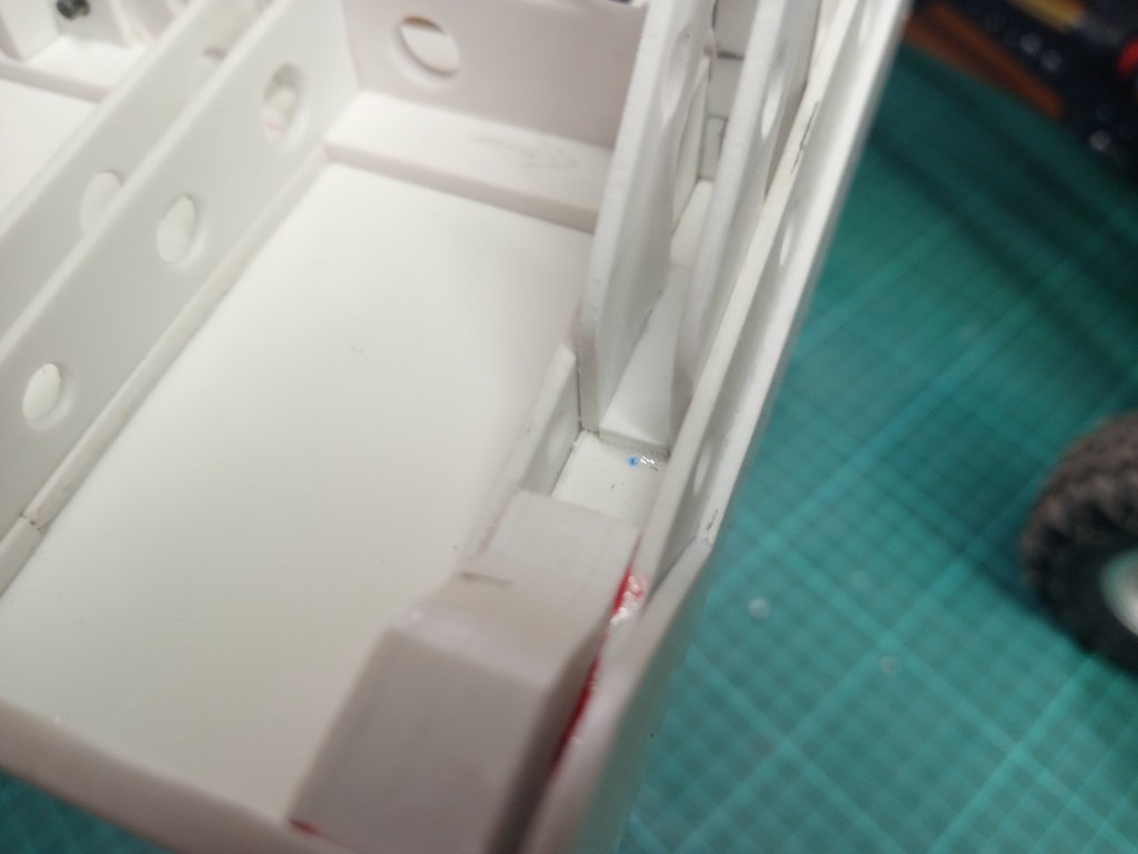
Der der bereits erwähnte Abstandsstreifen, hier an seinem Bestimmungsort, angepasst und verklebt. Seine Funktion; etwas Stabilität, aber hauptsächlich die Stützelemente beim Kleben an das U-Profil zu pressen.
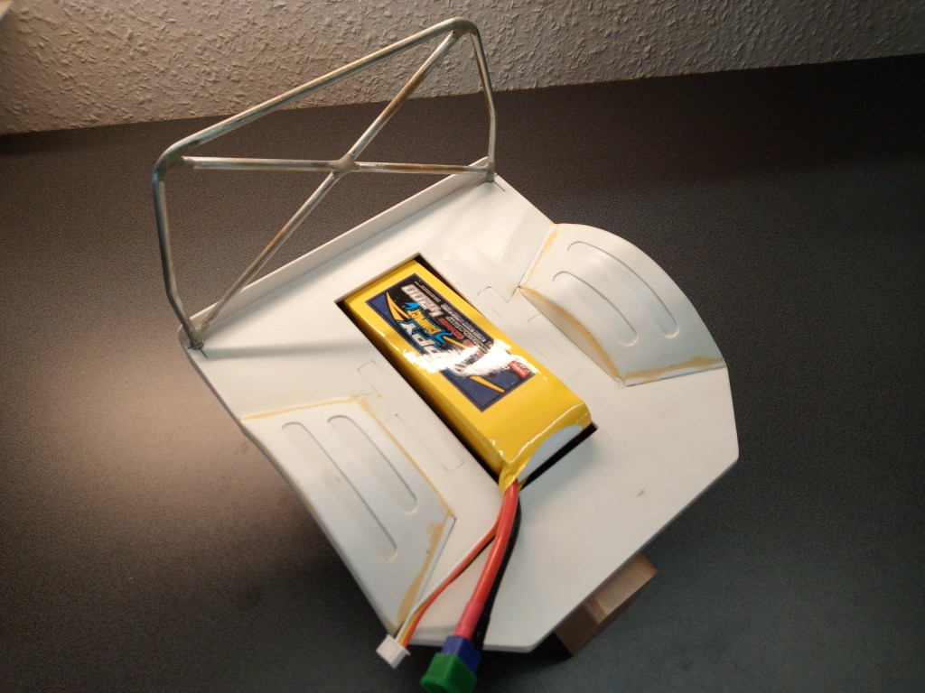
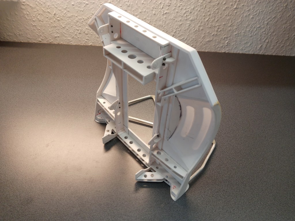
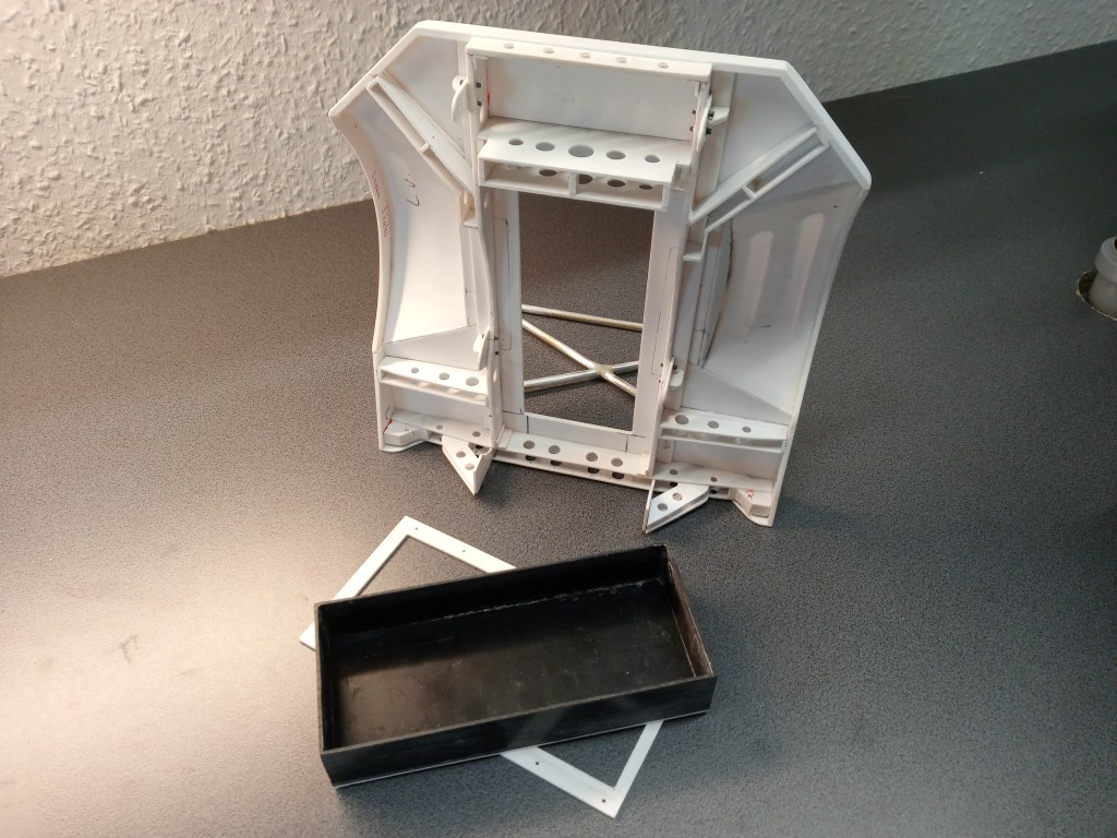
Zum Abschluss noch einige Bilder des gegenwärtigen Baustandes, in einer Fotoshow…

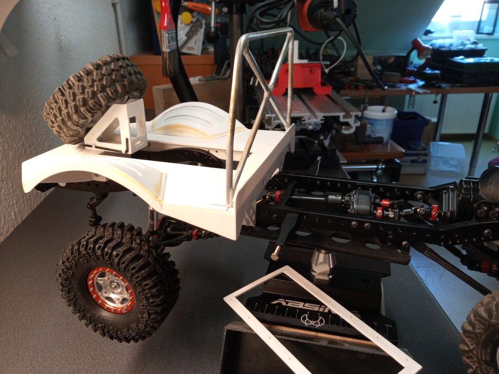
Wird schnellstmöglich fortgesetzt…
English Version
Filigree construction sites for detail design
Sources: RC4WD, Architekturversand.de
I had already presented a picture with small M2 screws. However, their appearance was anything but true to scale.
Therefore I had bought a selection of RC4WD micro screws. The screws have a collar and a hexagonal head, with a wrench size of 2 mm. Available with different diameters, lengths and color.
Since the first attempt was not as accurate as desired, I had to give it a try. My idea; drill out the thread to 1.5 mm and glue in a PS pin with identical diameter. In the following photo already glued in, but still untrimmed.
With the cutter knife flush cut off and a repositioned M2 thread, that following result.
Now the result looks clean, the wrench size is realistic, I again poorer by some euros, but satisfied. Since the previously installed M3 screw was also banished, immediately after the identical method the existing hole drilled out to 5 mm and also closed. Since I still had other holes to close, the last order from my supplier Architekturversand was also somewhat more extensive. Round rods with diameters of 1.5 – 5.0 mm.
The process; pre-drill a core hole with a 1.6 mm drill bit and cut the M2 thread using a fine chuck.
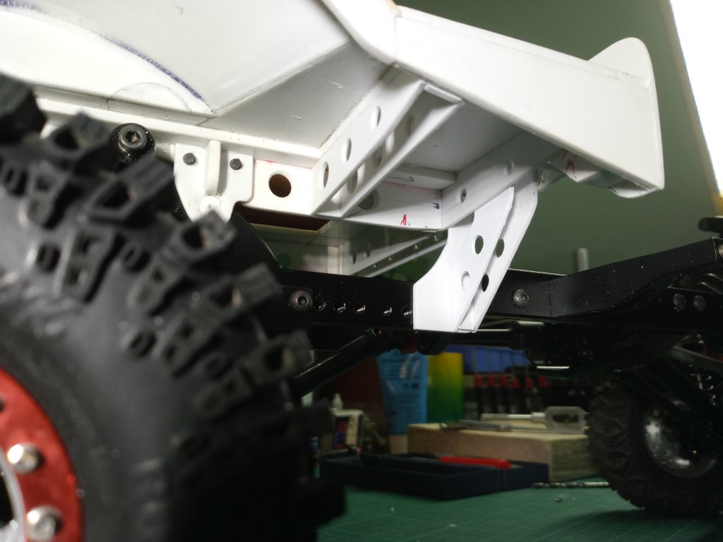
The appearance of the micro screws speaks for itself. However, these screws do not have any real holding function. The actual holder is glued to the subframe.
After grinding all 5 mm openings flush, the loading area is attached to the frame with 3.0 mm micro screws. Wrench size 2.5 mm corresponds in the original to a wrench size of approx. 21 mm. This is a realistic size. In comparison, the neighboring original screws. However, their replacement is not planned. After prolonged use in dirt and with oxidation, the small screw heads will probably not be able to transmit the necessary forces. Therefore, any existing threads in the frame are drilled out and a nut is mounted on the back.
Then some more hours of fine work for the front loading area holder. First, two PS pieces were bolted together. This way, two parts can be made in one operation.
After cutting out, holes were drilled for the optics. Each holder consists of a total of five components. The two main components in the following picture. In the center, the still uncut spacer strip to fix the two support elements in the existing U-profile.
Another component was needed for the screw connection to the frame. However, the hole that is still needed is not yet present here.
The already mentioned spacer strip, here at its destination, adapted and glued. Its function; to provide some stability, but mainly to press the support elements to the U-profile during gluing.
Finally, some pictures of the current state of construction, in a photo show….
Will be continued as soon as possible…
Translation, with the kind support of deepl.com
