English Version
In der Ladefläche gab es seit dem letzten Beitrag eine Aussparung. Der Zugang zum Fahrakku und zur Unterbringung der Lichtelektronik. Alles durch eine klappbare Abdeckung von oben zugänglich. Auch wird so ein schweres Bauteil in der Längsachse verteilt und zudem möglichst tief angeordnet. Seitlich Aufnahmen für drei Modulplatinen, zur Steuerung der Beleuchtung und ein Akku für den Antrieb müssen untergebracht werden. Los ging es also wieder mit dem schneiden von PS-Plattenstücken, die Stück für Stück untereinander verklebt wurden.

Die schwarze Bodenplatte alleine war sehr instabil und auch schlecht zu schneiden. Meine Messerklinge war nur mit großer Konzentration zu führen. Als Folge davon, musste ich teilweise noch schmale Streifen einkleben um den ungenauen Schnitt zu kaschieren. Aus Stabilitätsgründen wurde zunächst eine weitere PS-Platte unten angeklebt.
Und erst zum Abschluss die ursprüngliche Platte eingelegt und verklebt. Letztendlich wurden alle Überstände beigearbeitet. Die erste Anprobe im Fahrzeug brachte aber die Ernüchterung. Viel gemessen und doch passte es nicht! Die fertige Box war zu breit. 😯

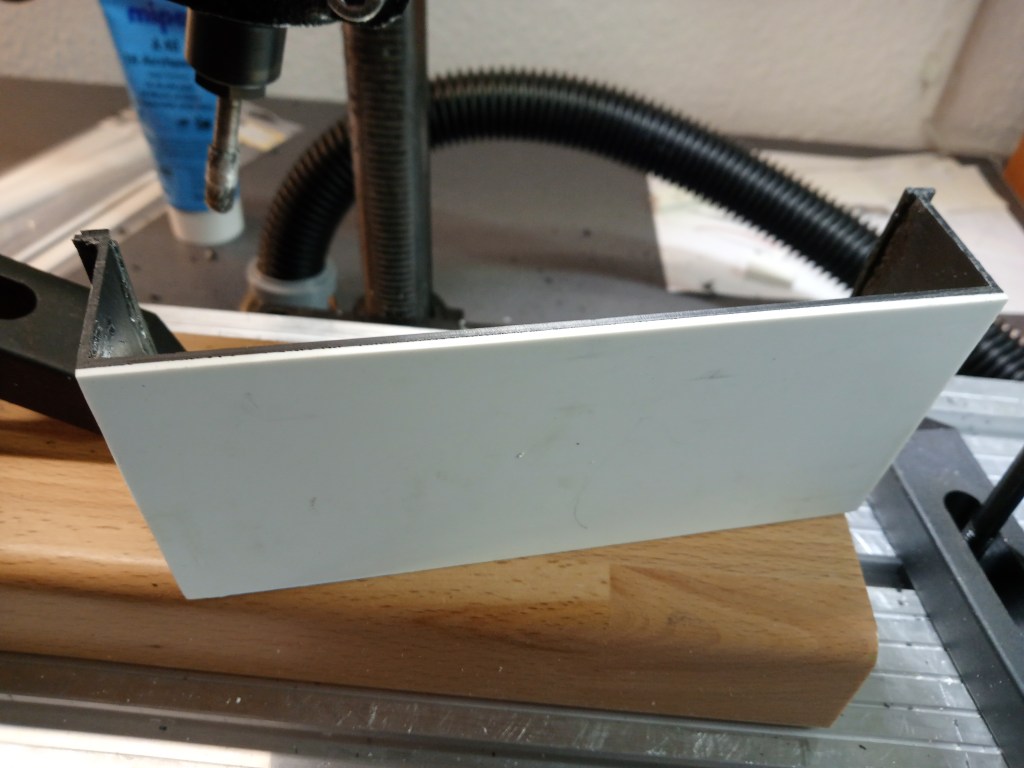
Jetzt gab es nur zwei Möglichkeiten. Neu bauen oder nachträglich schmäler machen. Die zweite Möglichkeit wurde schließlich in Angriff genommen. Da auch der schon verklebte obere Rand, nicht so nach meinen Vorstellungen geworden war, eine neue Gelegenheit den Fehler in meinem Sinn zu modifizieren. Also die Box auf dem Koordinatentisch befestigt und schrittweise auf die neue Breite abgefräst.

Nach der Fräsung eine in der Breite passende, plane Fläche.
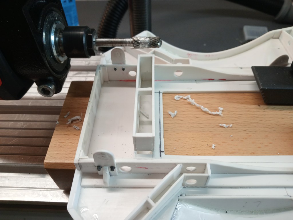
Für die noch einzupassende neue Seitenwand, Feinarbeit mit Fräser und Cuttermesser.

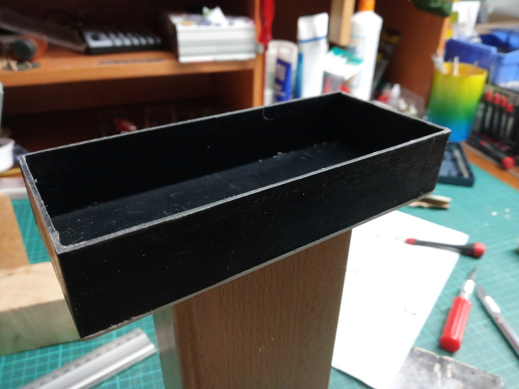
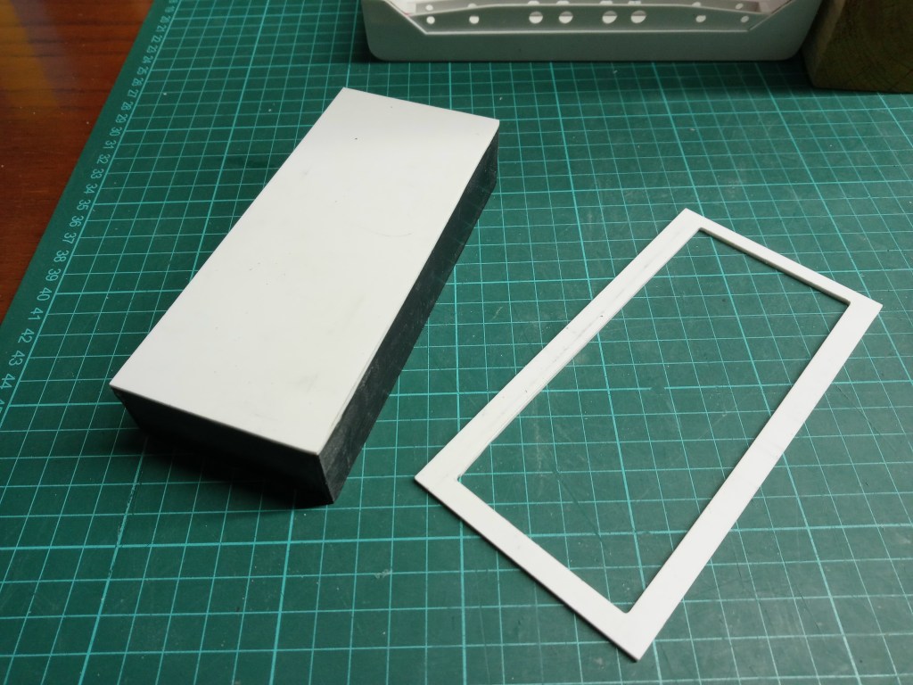
Abschließend wurde der obere Rand komplett abgefräst. Dafür werde ich einen neuen Bund herstellen, der auf der Innenseite mit der Box verklebt und außen mit der Ladefläche verschraubt wird. So bleibt für spätere Modifikationen genug Spielraum.
Der bereits horizontal ausgerichtete Fräser, wurde auch gleich noch für einen weiteren Schritt eingesetzt. Nachdem drei weitere Elemente in die hintere Ladeflächenführung eingeklebt wurden, stand noch eine horizontale Begradigung dieses Bauteils an. Das Bauteil ist nun biegesteif und passgenau. Eine Verschraubung mit dem Rahmen wäre fast entbehrlich, so sauber ist diese Führung gefertigt. 😎
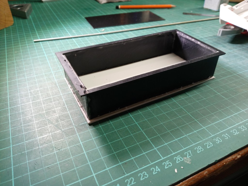
Der fertiggestellte Rand für die Akkubox.
Für die Befestigung unter der Ladefläche, warte ich noch auf passende Schrauben. Mehr davon in einem der folgenden Beiträge.
Wird schnellstmöglich fortgesetzt…
English Version
The battery and electronics box
There was a recess in the cargo area since the last post. The access to the drive battery and to accommodate the light electronics. All accessible from above through a hinged cover. Also, such a heavy component is distributed in the longitudinal axis and also arranged as low as possible. On the side, three module boards for controlling the lighting and a battery for the drive have to be accommodated. So we started again with the cutting of PS plate pieces, which were glued together piece by piece.
The black base plate alone was very unstable and also bad to cut. My knife blade could only be guided with great concentration. As a result, I had to glue in some narrow strips to conceal the imprecise cut. For stability reasons, another PS plate was glued to the bottom first.
And only at the end the original plate was inserted and glued. Finally, all overhangs were added. The first fitting in the vehicle brought disillusionment. A lot of measurements were taken, but it still didn’t fit! The finished box was too wide. 😯
Now there were only two options. Rebuild or make it narrower afterwards. The second option was finally tackled. Since also the already glued upper edge, had not become so according to my ideas, a new opportunity to modify the error in my sense. So the box was fixed on the coordinate table and milled step by step to the new width.
After milling, a flat surface matching in width.
For the new side panel still to be fitted, fine work with router and cutter knife.
Finally, the upper edge was completely milled off. For this I will make a new collar, which will be glued to the box on the inside and screwed to the loading area on the outside. This will leave enough room for later modifications.
The already horizontally aligned milling cutter, was also used for another step. After three more elements had been glued into the rear loading area guide, this component had to be straightened horizontally. The component is now rigid and fits perfectly. Screwing it to the frame would almost be superfluous, so neatly is this guide manufactured. 😎
The finished edge for the battery box.
For the attachment under the loading area, I’m still waiting for suitable screws. More of this in one of the following posts.
Will be continued as soon as possible…
Translation, with the kind support of deepl.com
