English Version
Die aktuelle Wetterlage; sehr hohe Luftfeuchtigkeit. Somit den Blick fest nach innen gerichtet und das war für die nächsten Bauschritt auch nötig. Aus zwei 2,5 mm starken PS-Platten, wurde im ersten Arbeitsschritt eine Aussparung herausgearbeitet, mit Koordinatentisch und Fräsmotor. Weniger dem Gewicht, als vielmehr der Optik geschuldet. Eine filigranere Optik sieht für mich einfach technischer und gleichzeitig auch schöner aus.

Im Anschluss wurde die äußere Form hergestellt.

Und das auch noch bei weiteren Bauteilen. Hier sieht man auch die ersten Aussparungen, die ich herausgefräst hatte, um einen besseren, statischen Verbund zu erzielen.

Hier schon einmal fixiert um die spätere Ansicht beurteilen zu können,…
… geht es danach gleich ins Finale. In insgesamt 5 Schritten wurden die Teile miteinander verklebt.
Die beiden Flächen in den Aussparungen, hatte ich mit etwas Materialzuschlag hergestellt. Da ich die Teile stückweise baute, sind Abweichungen im Zehntelbereich nicht ausgeschlossen. Was dann übersteht wird einfach nachgearbeitet. So sieht man auch hier den Materialüberschuss, an der eigentliche Aufnahmefläche des Reserverades.
Alle Bauteile sind verklebt!

Eine Hülse mit 4 mm Innengewinde und einem Bund, wurde in die Bohrung eingesetzt.
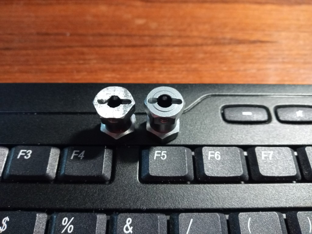
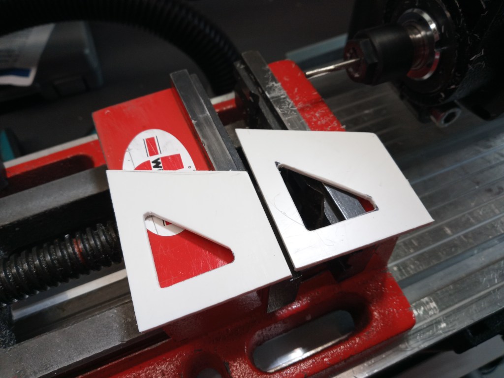
Eine 19 mm breite Vierkant-Aufnahme von GPM, als Ersatzteil für einen Radträger des Axial Bomber RR10, wurde plan gefräst. Links das bearbeitete und rechts das Originalteil.
Die bearbeitete Seite wurde auf die Hülsenmutter gesteckt.
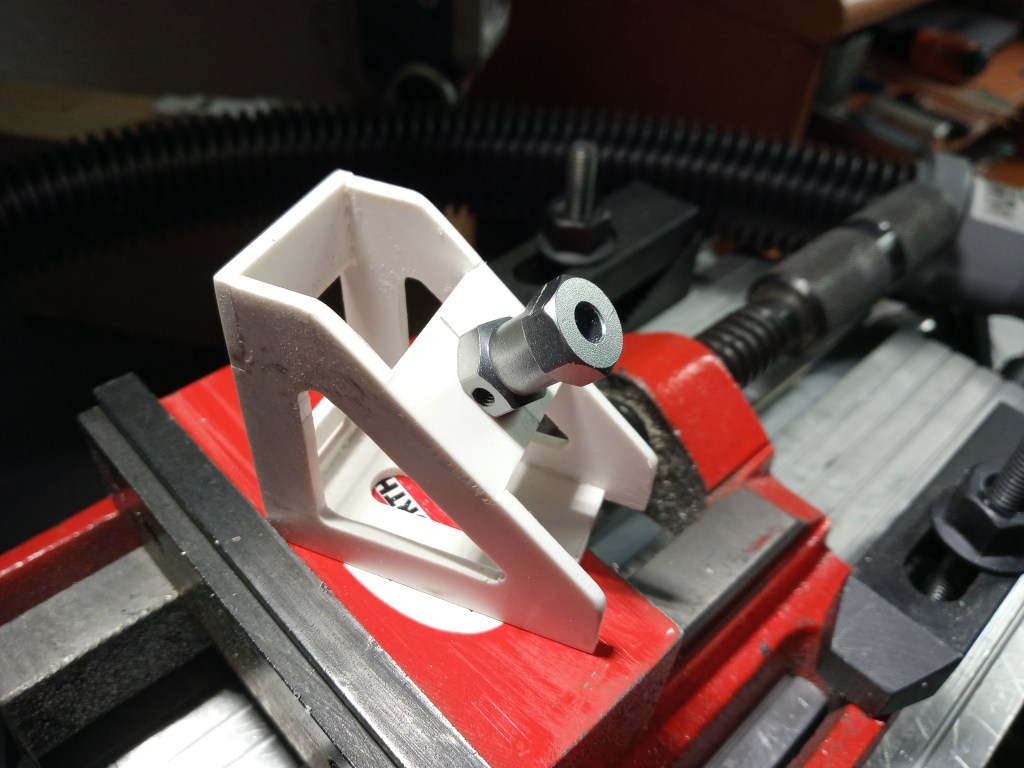
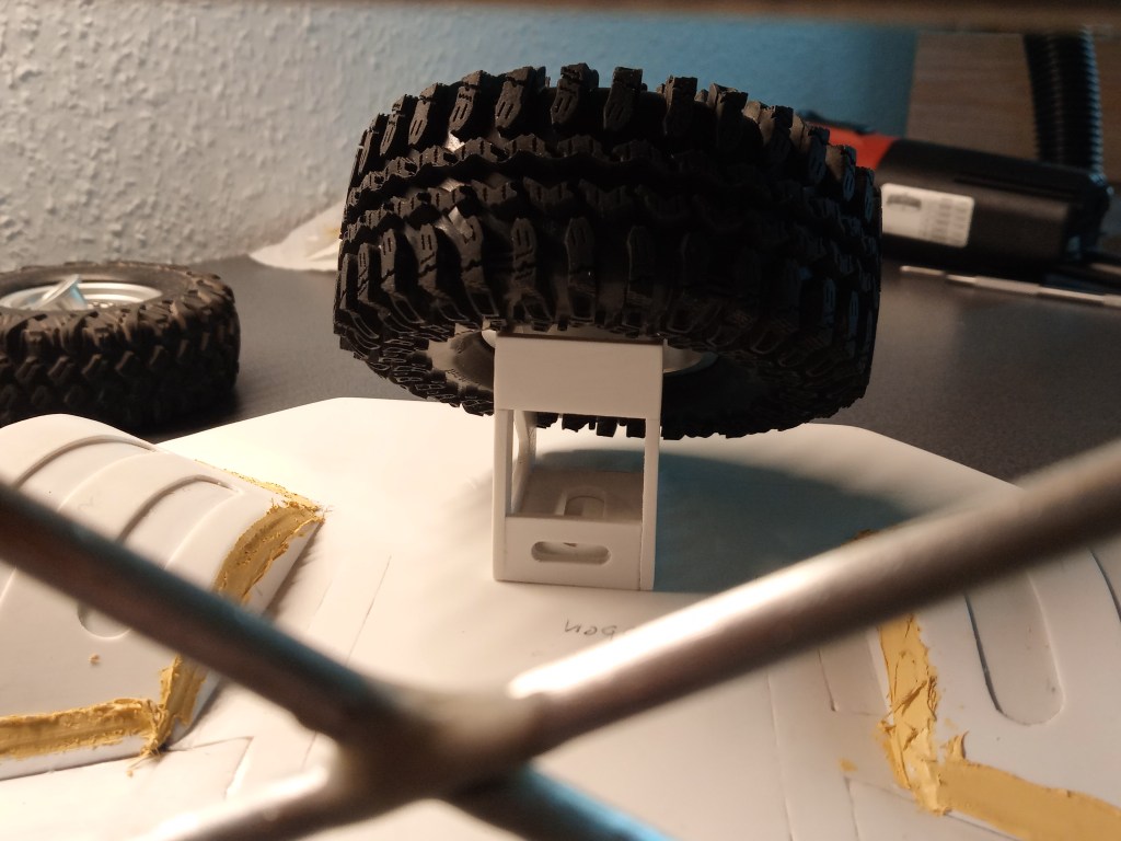
Hier sieht man nun den Aufbau auf der Unterseite. Der Bund der Hülsenmutter sorgte für einen Anschlag, gesichert mit zwei Madenschrauben. Aufgesteckt die eigentliche Sechskantaufnahme.
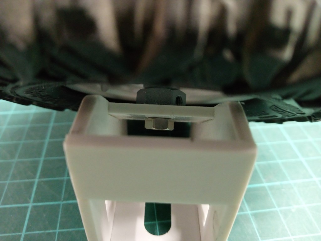
Von oben mit einer Inbusschraube gesichert. Diese Mutter erhält noch einen Schlitz, damit ein als V gebogener Draht als Knebel zum Öffnen eingeklebt werden kann.
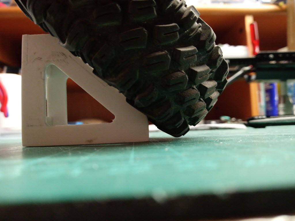
Wichtig auch, der Bodenabstand muss gewahrt sein, sonst steht die Konstruktion unter Spannung.
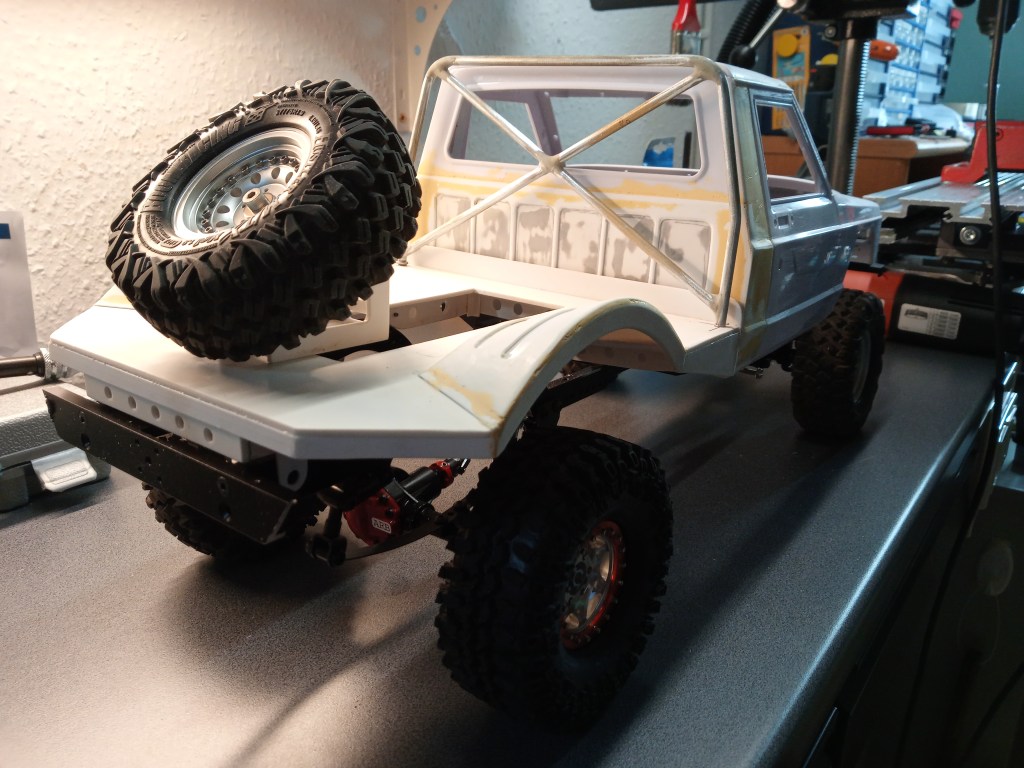
An seinem späteren Platz, sieht die Gesamtkonstruktion wie folgt aus. Darauf sieht man auch die erste Lage Feinspachtel. Es wird also wieder staubig…
Im Rahmen der Schleifarbeiten, wurde auch die Aussparung für den Akku herausgearbeitet. Darunter werde ich eine Box bauen, in der das Fahrakku eingelegt werden kann. Das sind dann die nächsten Bauschritte.

Der aktuelle Bauzustand.
Wird schnellstmöglich fortgesetzt…
English Version
Construction of the spare wheel holder
The current weather situation; very high humidity. Thus, the view firmly directed inward and that was also necessary for the next construction step. In the first step, a recess was carved out of two 2.5 mm thick PS plates, with a coordinate table and milling motor. Less for the weight, but rather for the optics. For me, a more filigree look simply looks more technical and at the same time more beautiful.
Subsequently, the outer form was produced.
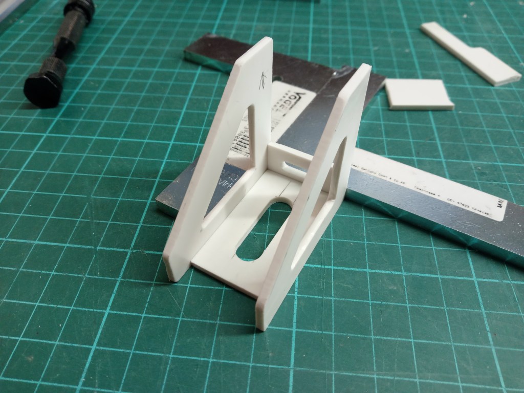
And this also with further components. Here you can also see the first recesses that I milled out to achieve a better, static bond.
Here already once fixed to be able to judge the later view,…
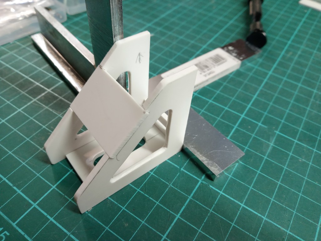
… then it goes directly into the final. The parts were glued together in a total of 5 steps.
The two surfaces in the recesses, I had made with some material surcharge. Since I built the parts piece by piece, deviations in the tenth range are not excluded. What is left over is simply reworked. You can see the excess material on the actual mounting surface of the spare wheel.
All parts are glued together!
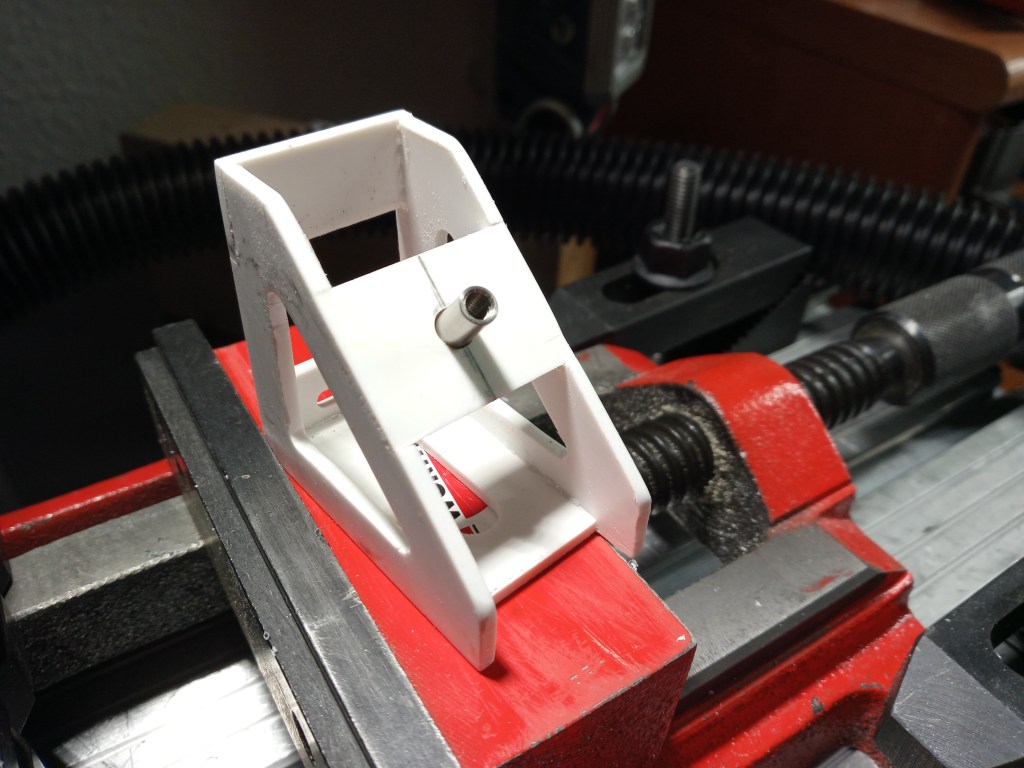
A sleeve with 4 mm internal thread and a collar, was inserted into the hole.
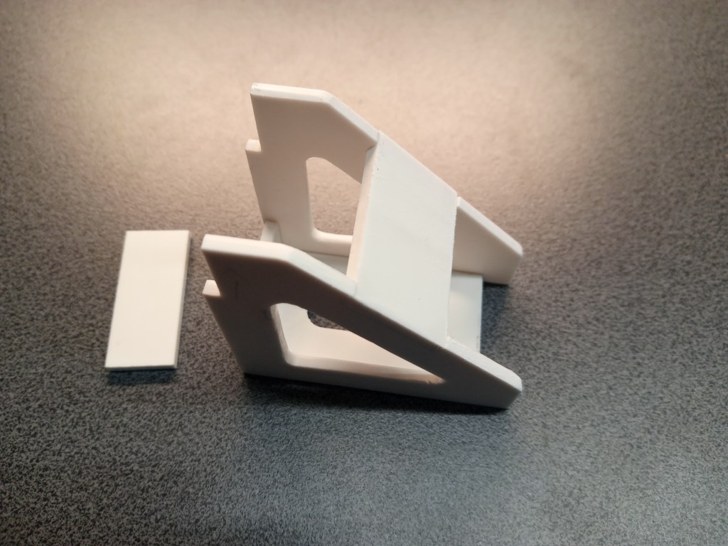
A 19 mm square mount from GPM, as a spare part for a wheel carrier of the Axial Bomber RR10, was milled flat. The machined part on the left and the original part on the right.
The machined side was put on the sleeve nut.
Here you can now see the assembly on the bottom side. The collar of the sleeve nut provided a stop, secured with two grub screws. The actual hexagonal socket was put on.
Secured from above with an Allen screw. This nut is given another slot so that a wire bent as a V can be glued in as a toggle for opening.
It is also important to maintain the distance to the floor, otherwise the construction will be under tension.
At its later place, the total construction looks as follows. On it you can also see the first layer of fine putty. So it will be dusty again…
As part of the sanding work, the recess for the battery was also worked out. Underneath I will build a box, in which the drive battery can be inserted. These are the next steps.
The current state of construction.
Will be continued as soon as possible…
Translation, with the kind support of deepl.com
