English Version
Einige sehr beschaulichen Tage sind leider vorüber. Keine Gedanken verschwenden, an die obligatorischen Wünsche für das neue Jahr. Meist bleibt es ohnehin bei den Vorsätzen. Es gibt auch so genug zu tun. Das Bauprogramm geht in die Fortsetzung. Die Befestigung der Ladefläche auf dem Rahmen, das Akkufach, die weitere Verstärkung der Radabdeckungen und letzte Arbeiten auf der Unterseite stehen als nächstes an.
Die folgenden Bauteile sind durchweg Reste aus dem gesammelten Kunststoffverschnitt. In einer Größe, die anderenorts als Fingernagelersatz verwendet wird, ist das Halten und Schneiden eine wirkliche Herausforderung. Zum Schutz meiner Finger, habe ich daher das sichere fixieren dem Maschinenschraubstock überlassen und die meisten Teile auf dem Koordinatentisch schrittweise auf Maß gefräst. Die Anschaffung, der Kombination von Bohrsäule und Koordinatentisch, war eine der besten Entscheidungen, die ich seit langer Zeit getroffen habe. 😃
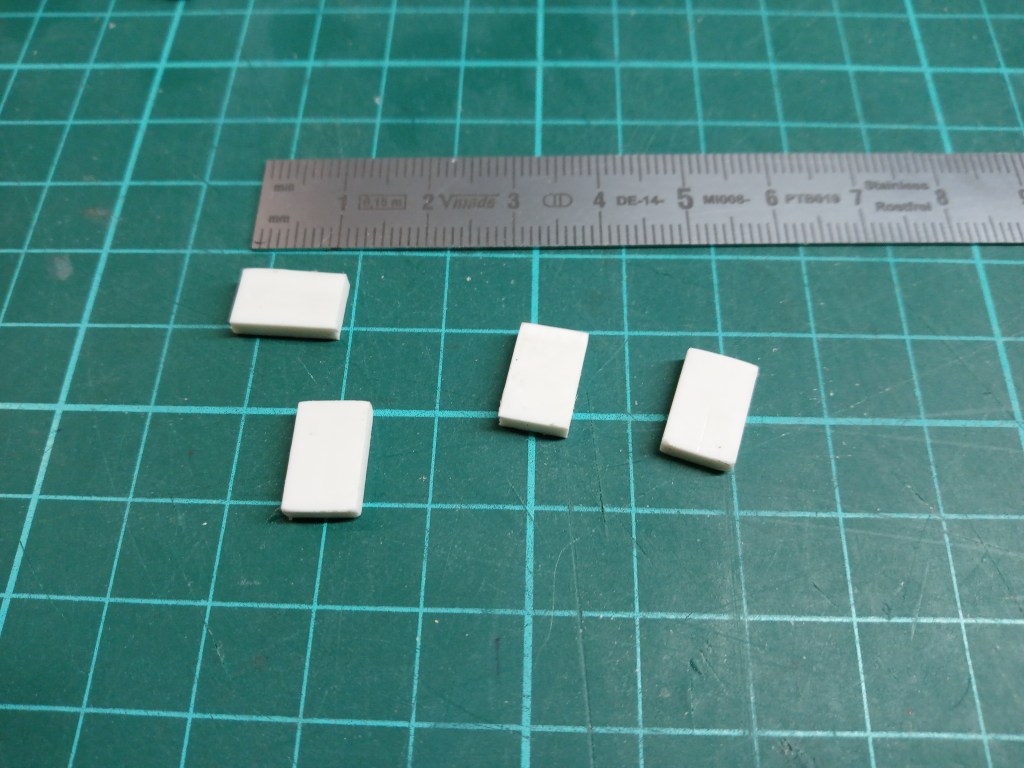
Die ersten Schritte, kleine Rechtecke. Abgerundet und schon gebohrt.
Weitere Teile und die auch noch etwas kleiner…
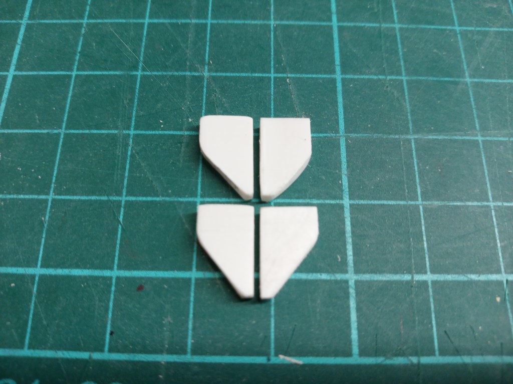
Und davon auch noch ein wenig abschneiden…
… und wieder kreativ fixieren, damit alles schön in Form bleibt.
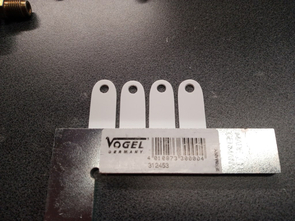
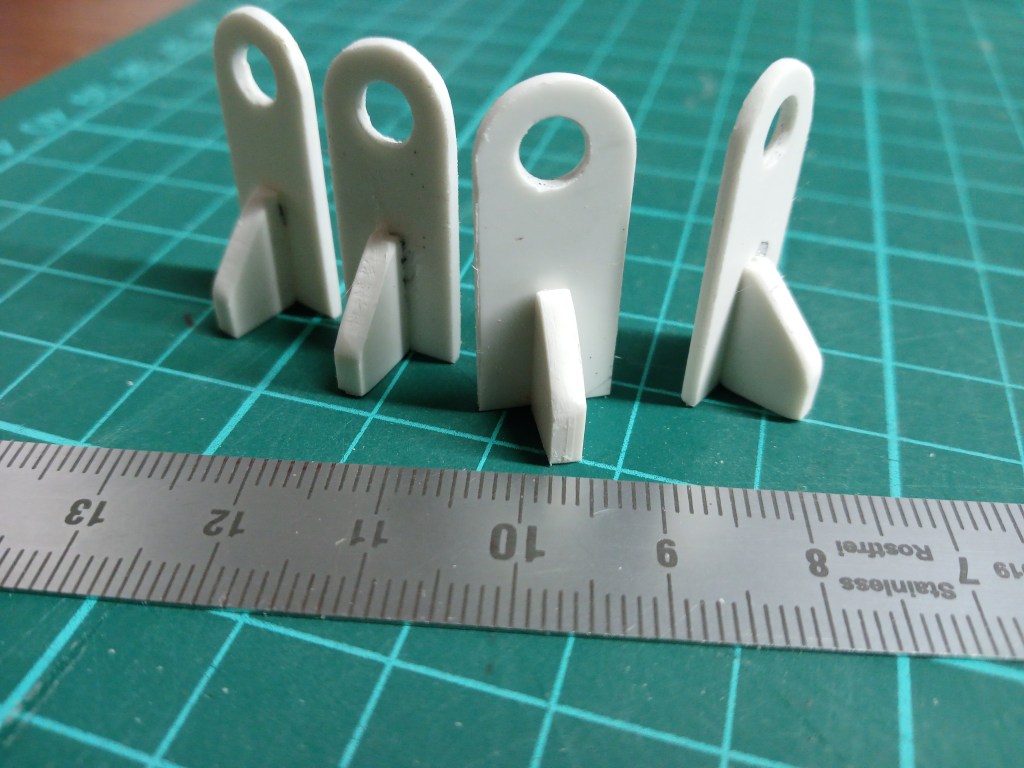
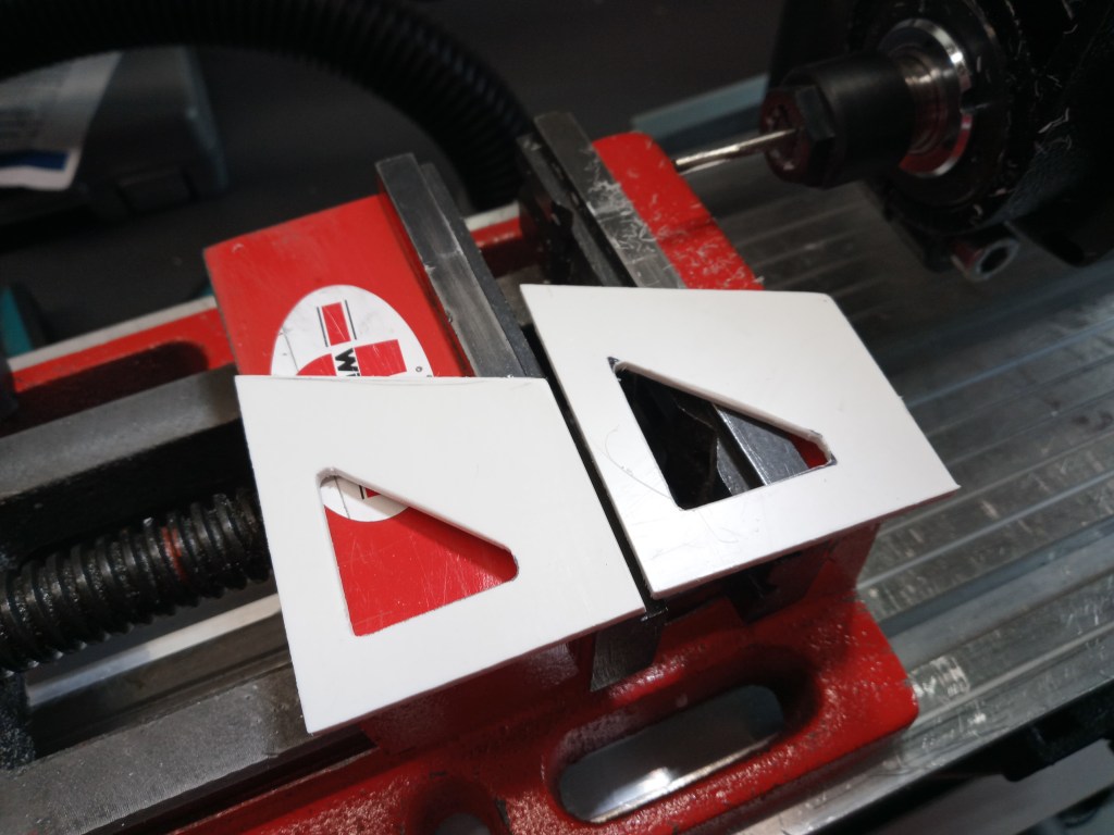
Das Ergebnis, die ersten Halterungen für die Befestigung von Aufbau und Rahmen. Zwei sind Reserve, benötigt werden davon nur die zwei perfektesten.
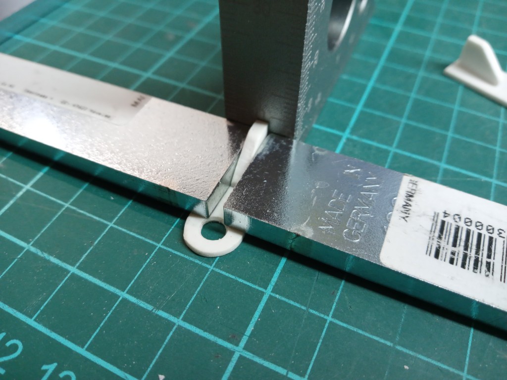
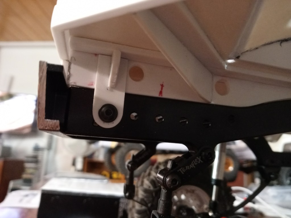
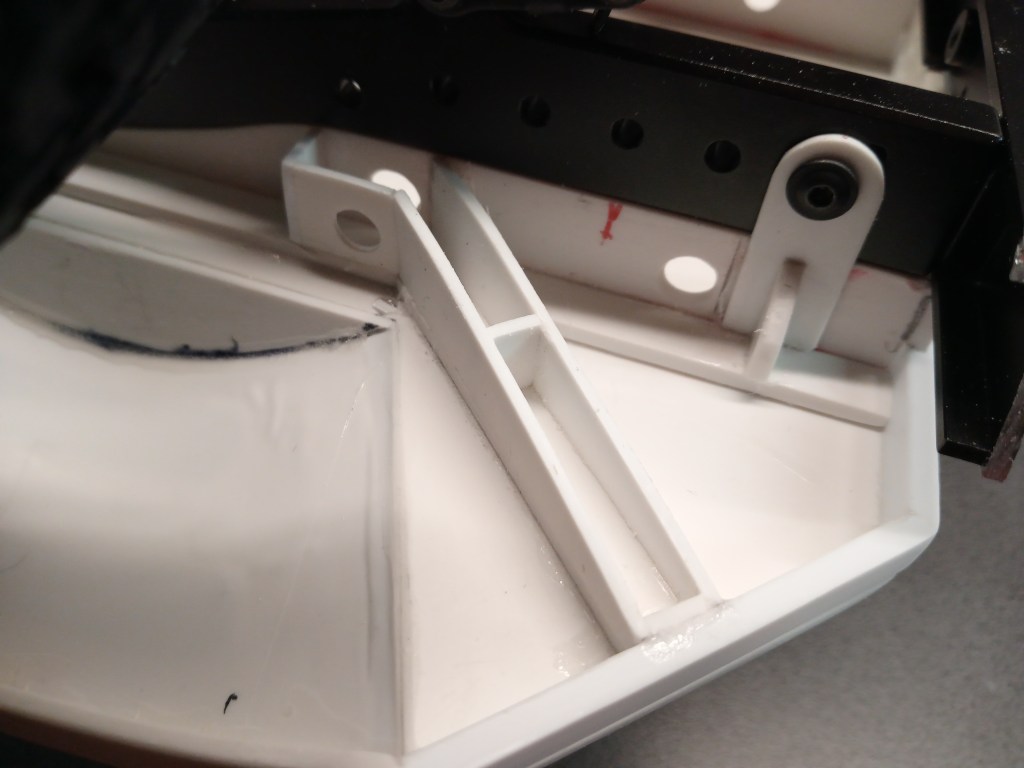
So wird die hintere Befestigung im Detail aussehen.
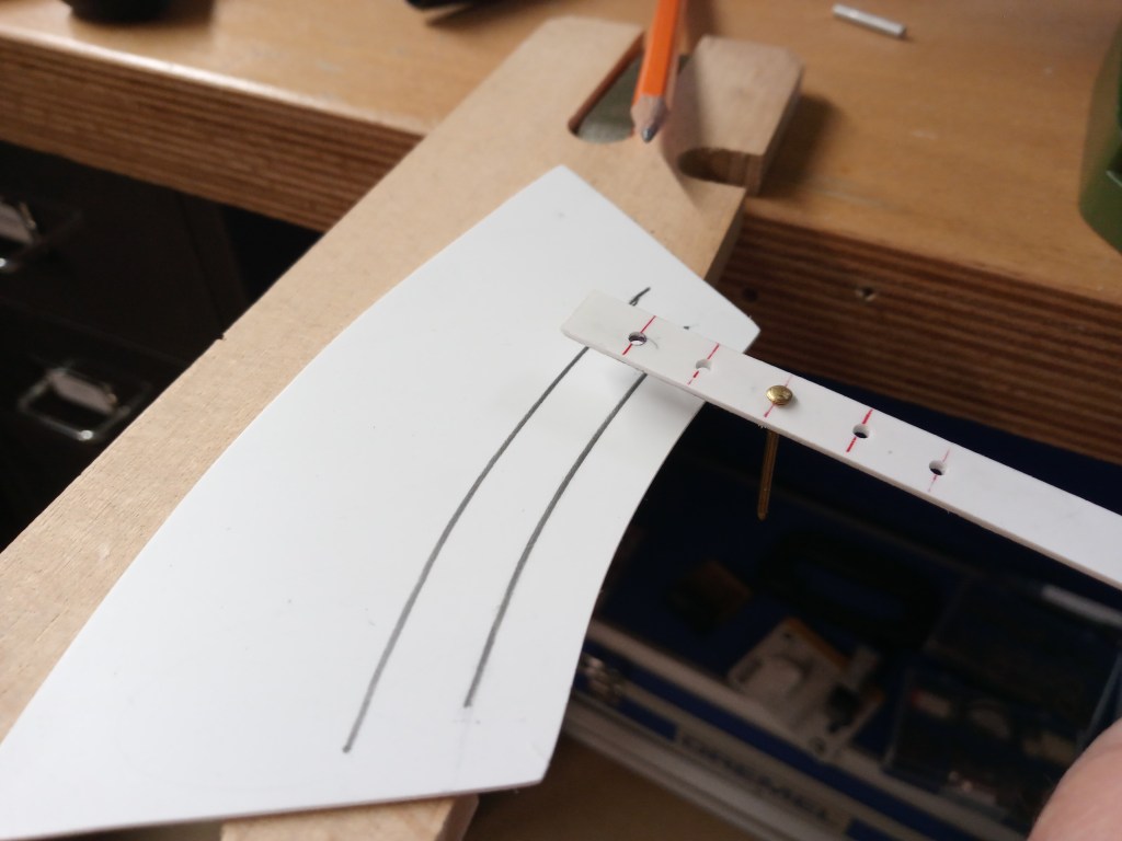
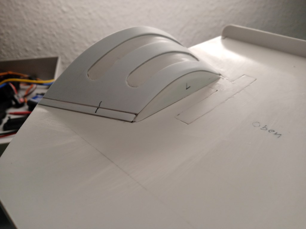
Bevor es damit weiter geht, ein weiterer Fortschritt an den hinteren Kotflügeln. Aus einer Papierschablone entstand eine weiteres Kotflügelelement, dieses Mal aus 1 mm starkem Polystyrol. Für die weiteren Bauschritte habe ich mir ein Hilfswerkzeug angefertigt. Der Nagel überträgt die vorhandene Rundung auf eine Bohrung, in der ein Bleistift geführt wird. Zurück bleiben vier parallel gespiegelte Kurven.
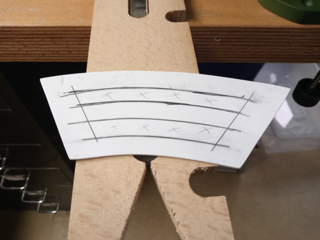
Daraus wurden zwei Felder ausgeschnitten und die Enden ausgebohrt. Eine zunächst noch sehr robuste Optik.

Nach einer Runde Feinarbeit hat sich die Ansicht aber stark verändert.

An seinem Platz, auf dem bisher nur 0,5 mm dünnen Kotflügel, verstärkt er nun nicht nur dessen Profil, sondern stellt auch ein realistischeres Bild dar.
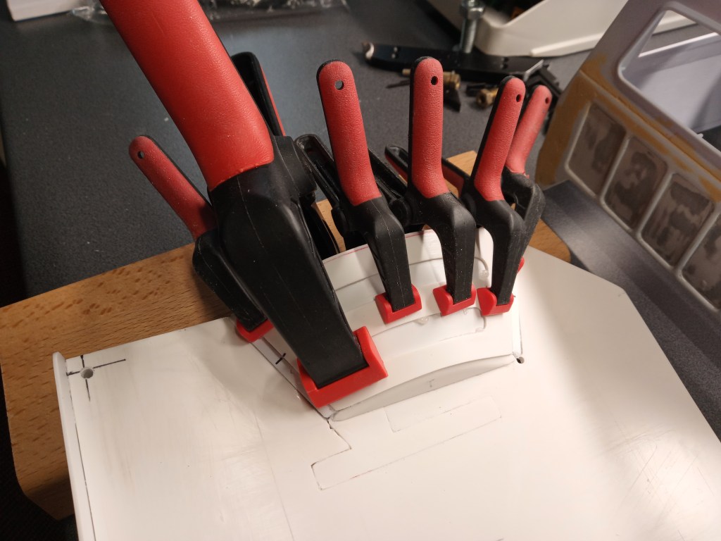
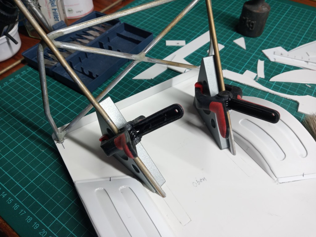
Dafür wurde es auch richtig in die Zange genommen. Dabei herausquellender Kleber, wird nach dem Entfernen der Spanner, mit einer flachen Klinge rückstandsfrei entfernt.
Für dem Messfehler beim Bau der Verstärkungsprofile am Heck, habe ich nachgearbeitet. Durch zwei zusätzlich eingebaute Elemente, wurde die Bohrung im Hauptrahmen erhalten und optisch etwas verstärkt. Vorher ein Winkelprofil …
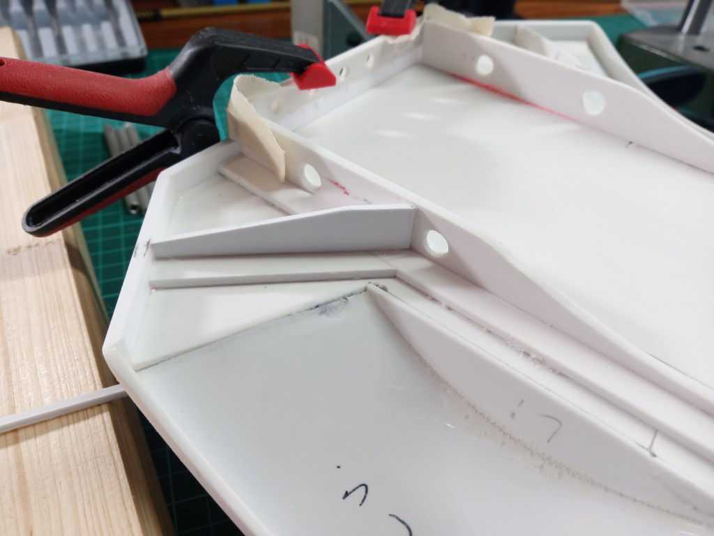
… und nach dem Umbau ein U-Profil, mit modifiziertem Anbindungspunkt.

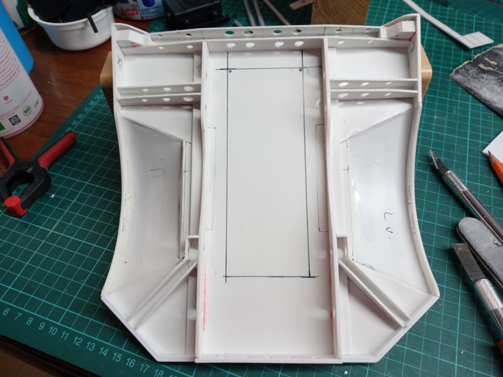
Und das symmetrisch auf beiden Seiten. Hier dann schon beigeschliffen und von den Stiftmarkierungen befreit. Angezeichnet, der auch noch herzustellende Ausschnitt für das Akkufach.
Aus Stabilitätsgründen wurden an den Enden der vier U-Profile, Verstärkungselemente eingeklebt. Weitere werden noch folgen.
Zusätzlich auch noch kleine Stützelemente in die hinteren U-Profilen.
Erste Anpassungsarbeiten, auch an den Stützbügeln des Überrollbügels.
Zum Abschluss die ersten Teile für den Reserveradhalter auf dem Truggyheck. Auf dem Koordinatentisch sauber ausgefräst.

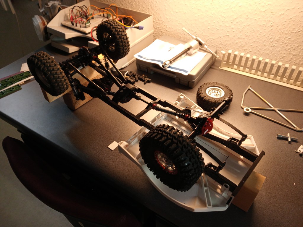
Im nächsten Beitrag wird u.a. der Reserveradhalter fertiggestellt und der Fahrzeugrahmen mit der Ladefläche verbunden. Vier Halterungen fehlen dazu noch. Zum Abschluss noch das obligatorische Foto des aktuellen Baustandes.
Wird schnellstmöglich fortgesetzt…
English Version
Other components for the truggy rear
Some very contemplative days are unfortunately over. Don’t waste any thought on the obligatory wishes for the new year. Mostly it remains with the resolutions anyway. There is enough to do as it is. The building programme continues. The attachment of the loading area to the frame, the battery compartment, the further reinforcement of the wheel covers and final work on the underside are next on the agenda.
The following components are all leftovers from the collected plastic scraps. In a size used elsewhere as a fingernail substitute, holding and cutting is a real challenge. To protect my fingers, I therefore left the secure fixing to the machine vice and milled most of the parts to size step by step on the coordinate table. The purchase of the combination of drill column and coordinate table was one of the best decisions I have made in a long time. 😃
The first steps, small rectangles. Rounded and already drilled.
More parts and those a bit smaller too….
And cutting off a bit of that too….
… and fix them creatively again, so that everything stays in shape.
The result, the first brackets for fixing the body and frame. Two are in reserve, only the two most perfect ones are needed.
This is what the rear attachment will look like in detail.
Before going on with that, another progress on the rear wings. From a paper template I made another wing element, this time from 1 mm thick polystyrene. For the further construction steps I made an auxiliary tool. The nail transfers the existing curve to a hole in which a pencil is guided. Four parallel mirrored curves remain.
From this, two fields were cut out and the ends drilled out. A very robust look at first.
After a round of fine-tuning, however, the view has changed considerably.
In its place, on the previously only 0.5 mm thin wing, it now not only reinforces its profile, but also presents a more realistic image.
To achieve this, it was also really put through its paces. After removing the clamps, any glue that oozes out is removed with a flat blade without leaving any residue.
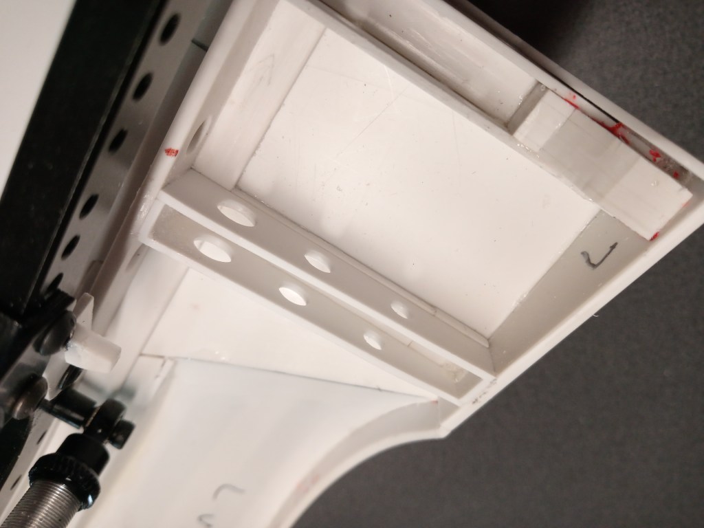
For the measuring error in the construction of the reinforcement profiles at the rear, I have reworked. With two additional elements, the hole in the main frame was preserved and optically strengthened. Before an angle profile …
… and after the modification a U-profile with a modified connection point.
And symmetrically on both sides. Here already sanded and freed from the pin markings. The cut-out for the battery compartment is also marked.
For stability reasons, reinforcing elements were glued to the ends of the four U-profiles. More will follow.
In addition, small support elements have been glued into the rear U-profiles.
First adjustment work, also on the supporting bars of the roll bar.
Finally the first parts for the spare wheel holder on the rear of the truggy. Cleanly milled out on the coordinate table.
In the next article the spare wheel holder will be finished and the vehicle frame will be connected to the cargo bed. Four brackets are still missing. Finally, the obligatory photo of the current state of construction.
Will be continued as soon as possible…
Translation, with the kind support of deepl.com
